4.6
SEL-749M Relay Instruction Manual Date Code 20080918
Protection and Logic Functions
Basic Motor Protection
Phase current transformers with 100:5 A rating are selected for the
application. The SEL-749M settings for the application are calculated
as shown below:
Current Transformer Ratio: CTR1 := 100/5 := 20 (see Main Settings
(SET Command))
Full Load Amps (FLA): FLA1 := 80 A primary (see Main Settings
(SET Command))
Service Factor: SF := 1.2
Locked Rotor Amps: LRA1 := 480.0/80.0 := 6.0 xFLA
Hot Locked Rotor Time: LRTHOT1 := 15.0 seconds
Run State Time Constant: RTC1 := Auto
The acceleration factor (TD1) setting reduces or extends the allowed
accelerating time under locked rotor conditions. You can always safely set this
value equal to 1.00.
If you know that the driven load will always accelerate in less than the rated
locked rotor time, you may wish to use a TD1 setting less than 1.00 to provide
a faster trip in locked rotor conditions. Do not, however, set the TD1 setting
greater than 1.00, except to allow a start with a longer than normal
accelerating time (e.g., high inertia motor application, emergency condition).
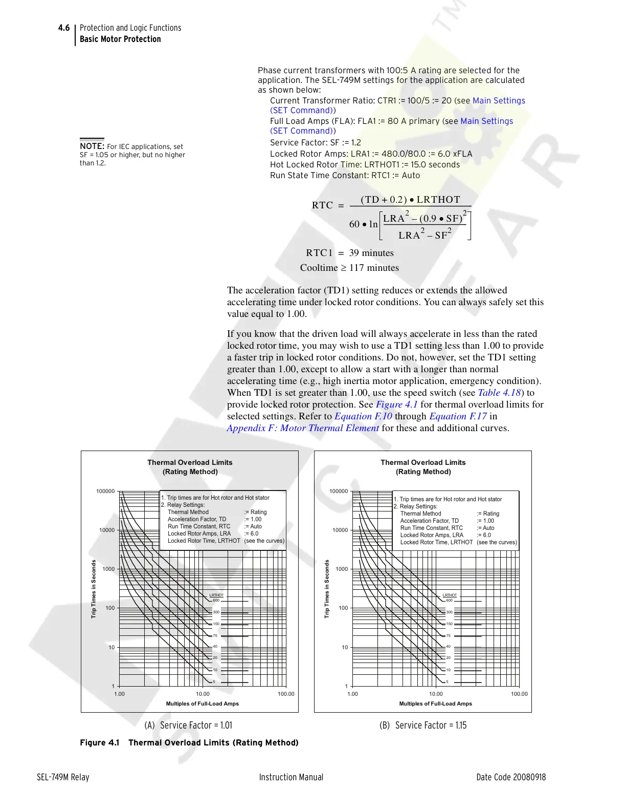
When TD1 is set greater than 1.00, use the speed switch (see Table 4.18) to
provide locked rotor protection. See Figure 4.1 for thermal overload limits for
selected settings. Refer to Equation F.10 through Equation F.17 in
Appendix F: Motor Thermal Element for these and additional curves.
Figure 4.1 Thermal Overload Limits (Rating Method)
NOTE: For IEC applications, set
SF = 1.05 or higher, but no higher
than 1.2.
RTC
TD 0.2+()LRTHOT•
60 ln
LRA
2
0.9 SF•()
2
–
LRA
2
SF
2
–
-------------------------------------------------
•
------------------------------------------------------------------------=
RTC1 39 minutes=
Cooltime 117 minutes≥
Thermal Overload Limits
(Rating Method)
1
10
100
1000
10000
100000
1.00 10.00 100.00
Multiples of Full-Load Amps
Trip Times in Seconds
600
300
150
75
40
20
10
5
LRTHOT
Thermal Overload Limits
(Rating Method)
1
10
100
1000
10000
100000
1.00 10.00 100.00
Multiples of Full-Load Amps
Trip Times in Seconds
600
300
150
75
40
20
10
5
LRTHOT
(A) Service Factor = 1.01 (B) Service Factor = 1.15
1. Trip times are for Hot rotor and Hot stator
2. Relay Settings:
Thermal Method := Rating
Acceleration Factor, TD := 1.00
Run Time Constant, RTC := Auto
Locked Rotor Amps, LRA := 6.0
Locked Rotor Time, LRTHOT (see the curves)
1. Trip times are for Hot rotor and Hot stator
2. Relay Settings:
Thermal Method := Rating
Acceleration Factor, TD := 1.00
Run Time Constant, RTC := Auto
Locked Rotor Amps, LRA := 6.0
Locked Rotor Time, LRTHOT (see the curves)
Courtesy of NationalSwitchgear.com