F.10
SEL-749M Relay Instruction Manual Date Code 20080918
Motor Thermal Element
Thermal Element Trip-Time Equations
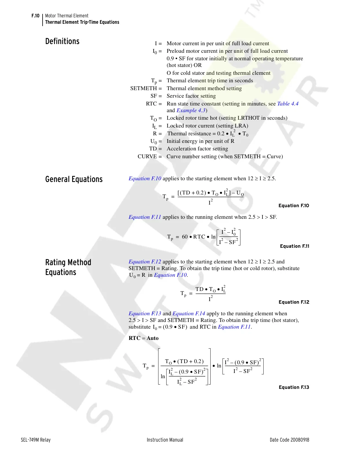
Definitions
General Equations
Equation F.10 applies to the starting element when 12 ≥ Ι ≥ 2.5.
Equation F.10
Equation F.11 applies to the running element when 2.5 > Ι > SF.
Equation F.11
Rating Method
Equations
Equation F.12 applies to the starting element when 12 ≥ Ι ≥ 2.5 and
SETMETH = Rating. To obtain the trip time (hot or cold rotor), substitute
in Equation F.10.
Equation F.12
Equation F.13 and Equation F.14 apply to the running element when
2.5 >Ι>SF and SETMETH = Rating. To obtain the trip time (hot stator),
substitute and RTC in Equation F.11.
RTC = Auto
Equation F.13
I = Motor current in per unit of full load current
I
0
= Preload motor current in per unit of full load current
0.9 • SF for stator initially at normal operating temperature
(hot stator) OR
O for cold stator and testing thermal element
T
p
= Thermal element trip time in seconds
SETMETH = Thermal element method setting
SF = Service factor setting
RTC = Run state time constant (setting in minutes, see Table 4.4
and Example 4.3)
T
O
= Locked rotor time hot (setting LRTHOT in seconds)
I
L
= Locked rotor current (setting LRA)
R=
U
0
= Initial energy in per unit of R
TD = Acceleration factor setting
CURVE = Curve number setting (when SETMETH = Curve)
Thermal resistance 0.2 I
L
2
• T
0
•=
T
p
TD 0.2+()T
O
• I
L
2
•[]U
O
–
I
2
--------------------------------------------------------------------=
T
p
60 RTC•
I
2
I
0
2
–
I
2
SF
2
–
-------------------
ln•=
U
0
R=
T
p
TD T
O
• I
L
2
•
I
2
-------------------------------=
I
0
0.9 SF•()=
T
p
T
O
TD 0.2+()•
I
L
2
0.9 SF•()
2
–
I
L
2
SF
2
–
--------------------------------------
ln
-------------------------------------------------
I
2
0.9 SF•()
2
–
I
2
SF
2
–
-------------------------------------
ln•=
Courtesy of NationalSwitchgear.com
 Loading...


