F.3
Date Code 20080918 Instruction Manual SEL-749M Relay
Motor Thermal Element
The Basic Thermal Element
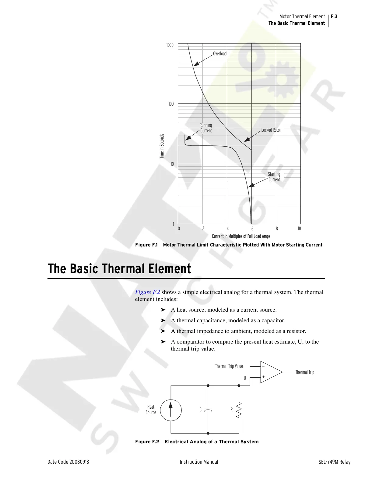
Figure F.1
Motor Thermal Limit Characteristic Plotted With Motor Starting Current
The Basic Thermal Element
Figure F.2 shows a simple electrical analog for a thermal system. The thermal
element includes:
➤ A heat source, modeled as a current source.
➤ A thermal capacitance, modeled as a capacitor.
➤ A thermal impedance to ambient, modeled as a resistor.
➤ A comparator to compare the present heat estimate, U, to the
thermal trip value.
Figure F.2 Electrical Analog of a Thermal System
0246810
1
10
100
Current in Multi
les of Full Load Am
s
Time in Seconds
1000
Overload
Running
Current
Locked Rotor
Starting
Current
Thermal Trip
Thermal Trip Value
+
—
Heat
Source
U
CR
Courtesy of NationalSwitchgear.com