2.2
SEL-749M Relay Instruction Manual Date Code 20080918
Installation
I/O Configuration
Relay Mounting
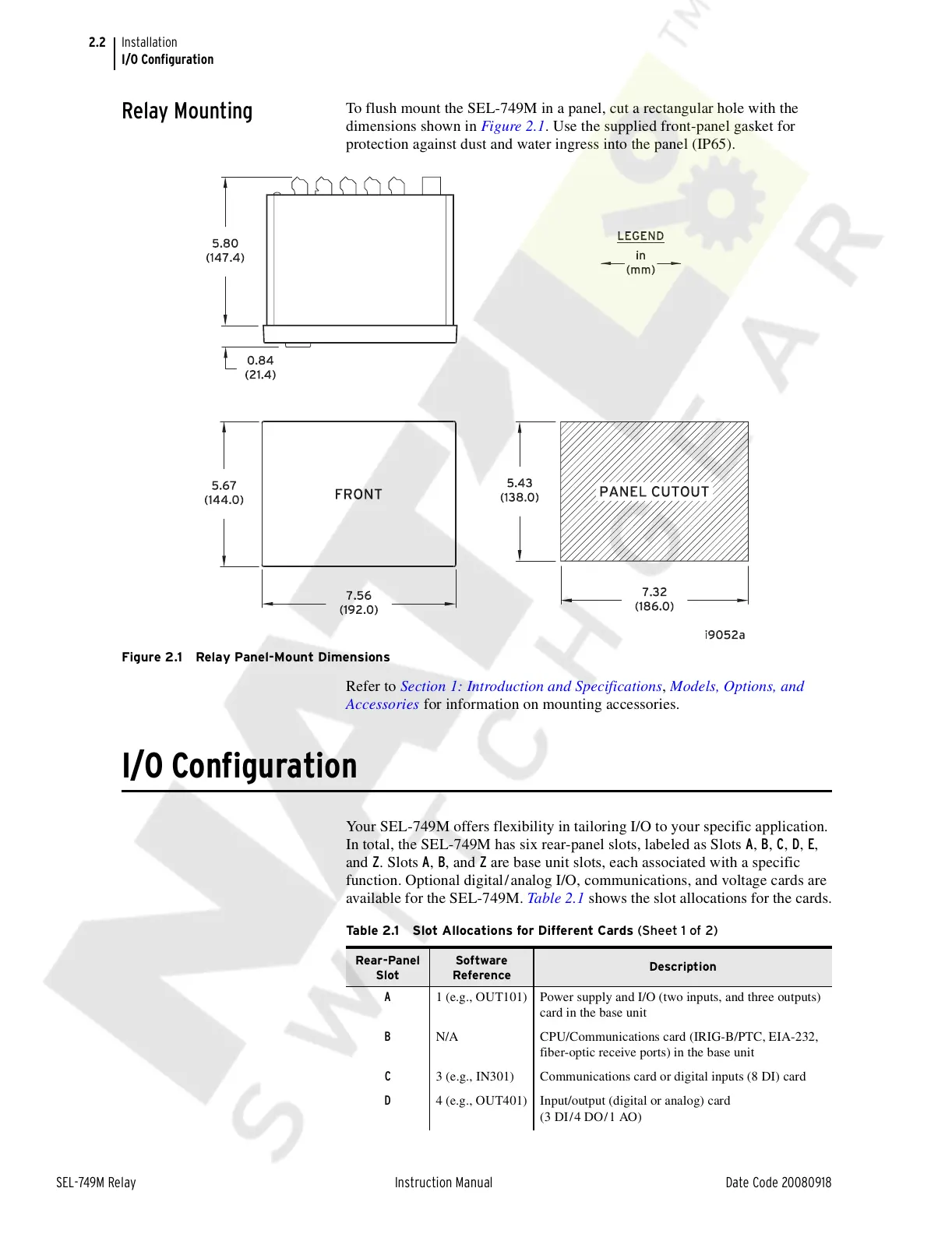
To flush mount the SEL-749M in a panel, cut a rectangular hole with the
dimensions shown in Figure 2.1. Use the supplied front-panel gasket for
protection against dust and water ingress into the panel (IP65).
Figure 2.1 Relay Panel-Mount Dimensions
Refer to Section 1: Introduction and Specifications, Models, Options, and
Accessories for information on mounting accessories.
I/O Configuration
Your SEL-749M offers flexibility in tailoring I/O to your specific application.
In total, the SEL-749M has six rear-panel slots, labeled as Slots A, B, C, D, E,
and Z. Slots A, B, and Z are base unit slots, each associated with a specific
function. Optional digital/analog I/O, communications, and voltage cards are
available for the SEL-749M. Table 2.1 shows the slot allocations for the cards.
Table 2.1 Slot Allocations for Different Cards (Sheet 1 of 2)
Rear-Panel
Slot
Software
Reference
Description
A 1 (e.g., OUT101) Power supply and I/O (two inputs, and three outputs)
card in the base unit
B N/A CPU/Communications card (IRIG-B/PTC, EIA-232,
fiber-optic receive ports) in the base unit
C 3 (e.g., IN301) Communications card or digital inputs (8 DI) card
D 4 (e.g., OUT401) Input/output (digital or analog) card
(3 DI/4 DO/1 AO)
Courtesy of NationalSwitchgear.com