2.12
SEL-749M Relay Instruction Manual Date Code 20080918
Installation
Rear-Panel Connections
I/O Diagram
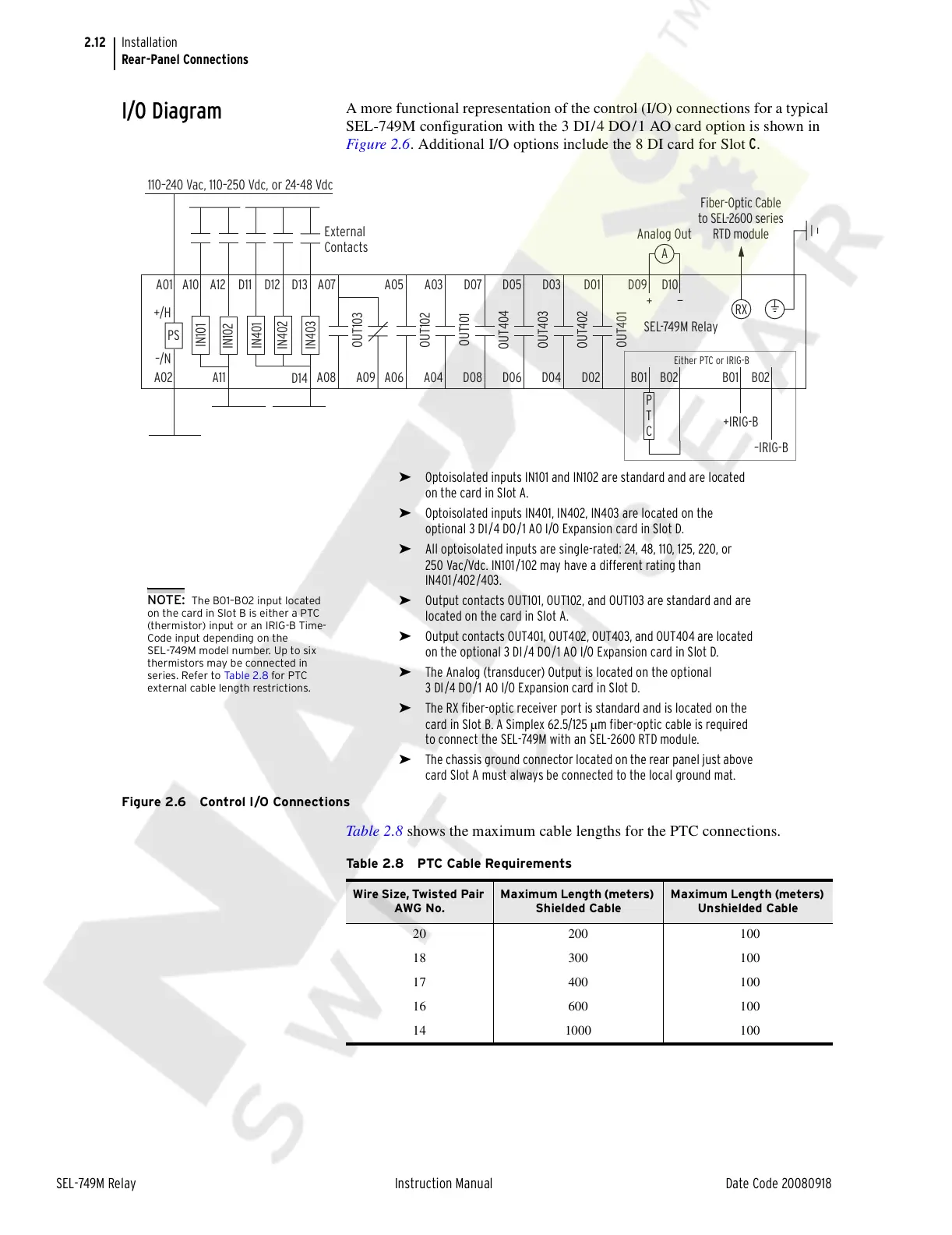
A more functional representation of the control (I/O) connections for a typical
SEL-749M configuration with the 3 DI/4 DO/1 AO card option is shown in
Figure 2.6. Additional I/O options include the 8 DI card for Slot C.
Figure 2.6 Control I/O Connections
Table 2.8 shows the maximum cable lengths for the PTC connections.
+IRIG-B
–IRIG-B
Either PTC or IRIG-B
PS
A01
A02
–/N
+/H
110–240 Vac, 110–250 Vdc, or 24-48 Vdc
External
Contacts
SEL-749M Relay
RX
A
D09
Analog Out
—
+
D10
B01 B02 B01 B02
IN101
IN102
IN401
IN402
IN403
A10
A11
A12 D11 D12
D14
D13
P
T
C
A07
A08
OUT103
D03
D04
OUT402
D01
D02
OUT401
D05
D06
OUT403
D07
D08
OUT404
A03
A04
OUT101
A05
A06
OUT102
A09
Fiber-Optic Cable
to SEL-2600 series
RTD module
➤ Optoisolated inputs IN101 and IN102 are standard and are located
on the card in Slot A.
➤ Optoisolated inputs IN401, IN402, IN403 are located on the
optional 3 DI/4 DO/1 AO I/O Expansion card in Slot D.
➤ All optoisolated inputs are single-rated: 24, 48, 110, 125, 220, or
250 Vac/Vdc. IN101/102 may have a different rating than
IN401/402/403.
➤ Output contacts OUT101, OUT102, and OUT103 are standard and are
located on the card in Slot A.
➤ Output contacts OUT401, OUT402, OUT403, and OUT404 are located
on the optional 3 DI/4 DO/1 AO I/O Expansion card in Slot D.
➤ The Analog (transducer) Output is located on the optional
3 DI/4 DO/1 AO I/O Expansion card in Slot D.
➤ The RX fiber-optic receiver port is standard and is located on the
card in Slot B. A Simplex 62.5/125 µm fiber-optic cable is required
to connect the SEL-749M with an SEL-2600 RTD module.
➤ The chassis ground connector located on the rear panel just above
card Slot A must always be connected to the local ground mat.
NOTE: The B01–B02 input located
on the card in Slot B is either a PTC
(thermistor) input or an IRIG-B Time-
Code input depending on the
SEL-749M model number. Up to six
thermistors may be connected in
series. Refer to Ta bl e 2 .8 for PTC
external cable length restrictions.
Table 2.8 PTC Cable Requirements
Wire Size, Twisted Pair
AWG No.
Maximum Length (meters)
Shielded Cable
Maximum Length (meters)
Unshielded Cable
20 200 100
18 300 100
17 400 100
16 600 100
14 1000 100
Courtesy of NationalSwitchgear.com