7.3
Date Code 20080918 Instruction Manual SEL-749M Relay
Communications
Communications Interfaces
Port Connector and
Communications
Cables
Figure 7.1 shows the front-panel EIA-232 serial port (PORT F) DB-9 connector
pinout for the SEL-749M.
Figure 7.1 EIA-232 DB-9 Connector Pin Numbers
Table 7.2 shows the pin functions for the EIA-232 and EIA-485 serial ports.
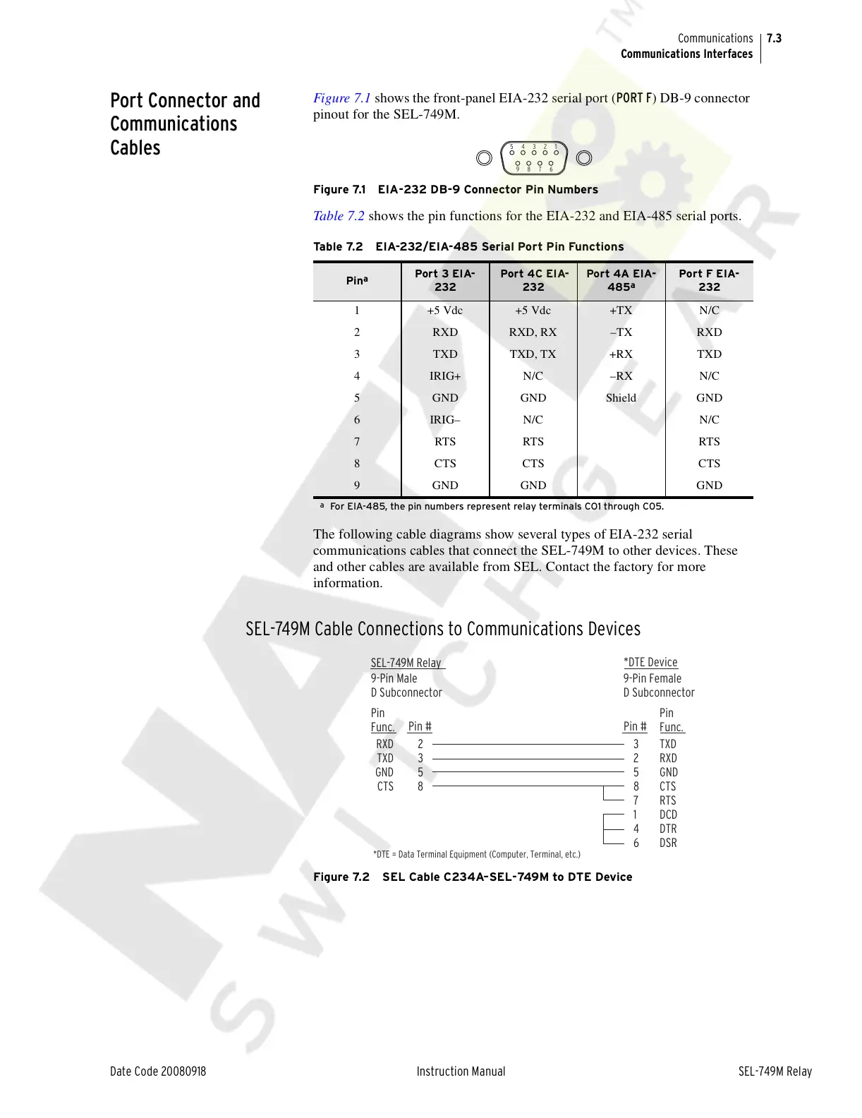
The following cable diagrams show several types of EIA-232 serial
communications cables that connect the SEL-749M to other devices. These
and other cables are available from SEL. Contact the factory for more
information.
SEL-749M Cable Connections to Communications Devices
Figure 7.2 SEL Cable C234A–SEL-749M to DTE Device
Table 7.2 EIA-232/EIA-485 Serial Port Pin Functions
Pin
a
a
For EIA-485, the pin numbers represent relay terminals CO1 through C05.
Port 3 EIA-
232
Port 4C EIA-
232
Port 4A EIA-
485
a
Port F EIA-
232
1 +5 Vdc +5 Vdc +TX N/C
2 RXD RXD, RX –TX RXD
3 TXD TXD, TX +RX TXD
4 IRIG+ N/C –RX N/C
5 GND GND Shield GND
6IRIG–N/C N/C
7 RTS RTS RTS
8 CTS CTS CTS
9 GND GND GND
5 4 3 2 1
9 8 7 6
SEL-749M Relay
9-Pin Male
D Subconnector
9-Pin Female
D Subconnector
2
3
5
8
3
2
5
8
7
1
4
6
RXD
TXD
GND
CTS
TXD
RXD
GND
CTS
RTS
DCD
DTR
DSR
Pin
Func.
Pin
Func.
Pin # Pin #
*DTE Device
*DTE = Data Terminal Equipment (Computer, Terminal, etc.)
Courtesy of NationalSwitchgear.com