4.38
SEL-749M Relay Instruction Manual Date Code 20080918
Protection and Logic Functions
Logic Settings (SET L Command)
motor applications. You can also use this input to change the settings in
applications where ambient temperature varies appreciably (e.g., exposed
water pumps with different capacities during daytime and at night).
The SPEEDSW control input provides an indication of the rotor speed to the
speed switch logic. Speed Switch (Stalling During Start) Function on
page 4.20 for more detail.
Logic Settings (SET L Command)
NOTE: SV in the Setting Range
column of the settings tables indicates
SEL
OGIC control equation.
Settings associated with latches, timers, and output contacts are listed below.
Logic Functions on page 4.45 explains the settings and operation of the logic
input/output and the SEL
OGIC control equations of the SEL-749M.
SELOGIC Enables
The enable settings ELAT and ESV control the settings shown in Table 4.35
and Table 4.36. This helps limit the number of settings that need to be made.
Latch Bits Equations
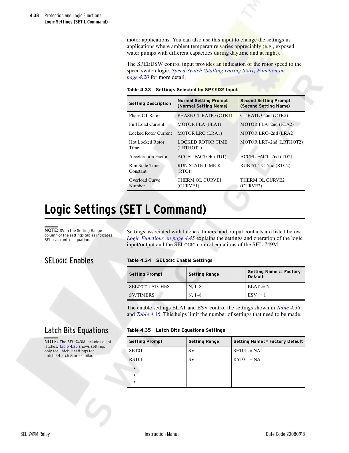
Table 4.33 Settings Selected by SPEED2 Input
Setting Description
Normal Setting Prompt
(Normal Setting Name)
Second Setting Prompt
(Second Setting Name)
Phase CT Ratio PHASE CT RATIO (CTR1) CT RATIO–2nd (CTR2)
Full Load Current MOTOR FLA (FLA1) MOTOR FLA–2nd (FLA2)
Locked Rotor Current MOTOR LRC (LRA1) MOTOR LRC–2nd (LRA2)
Hot Locked Rotor
Time
LOCKED ROTOR TIME
(LRTHOT1)
MOTOR LRT–2nd (LRTHOT2)
Acceleration Factor ACCEL FACTOR (TD1) ACCEL FACT–2nd (TD2)
Run State Time
Constant
RUN STATE TIME K
(RTC1)
RUN ST TC–2nd (RTC2)
Overload Curve
Number
THERM OL CURVE1
(CURVE1)
THERM OL CURVE2
(CURVE2)
Ta b l e 4 . 34 S ELOGIC Enable Settings
Setting Prompt Setting Range
Setting Name := Factory
Default
SELOGIC LATCHES N, 1–8 ELAT := N
SV/TIMERS N, 1–8 ESV := 1
NOTE: The SEL-749M includes eight
latches. Ta bl e 4 .35 shows settings
only for Latch 1; settings for
Latch 2-Latch 8 are similar.
Table 4.35 Latch Bits Equations Settings
Setting Prompt Setting Range Setting Name := Factory Default
SET01 SV SET01 := NA
RST01 SV RST01 := NA
•
•
•
Courtesy of NationalSwitchgear.com

 Loading...


