Date Code 20080918 Instruction Manual SEL-749M Relay
Appendix A
Firmware and Manual Versions
Instructi on Manual
Firmware
Determining the
Firmware Version
in Your Relay
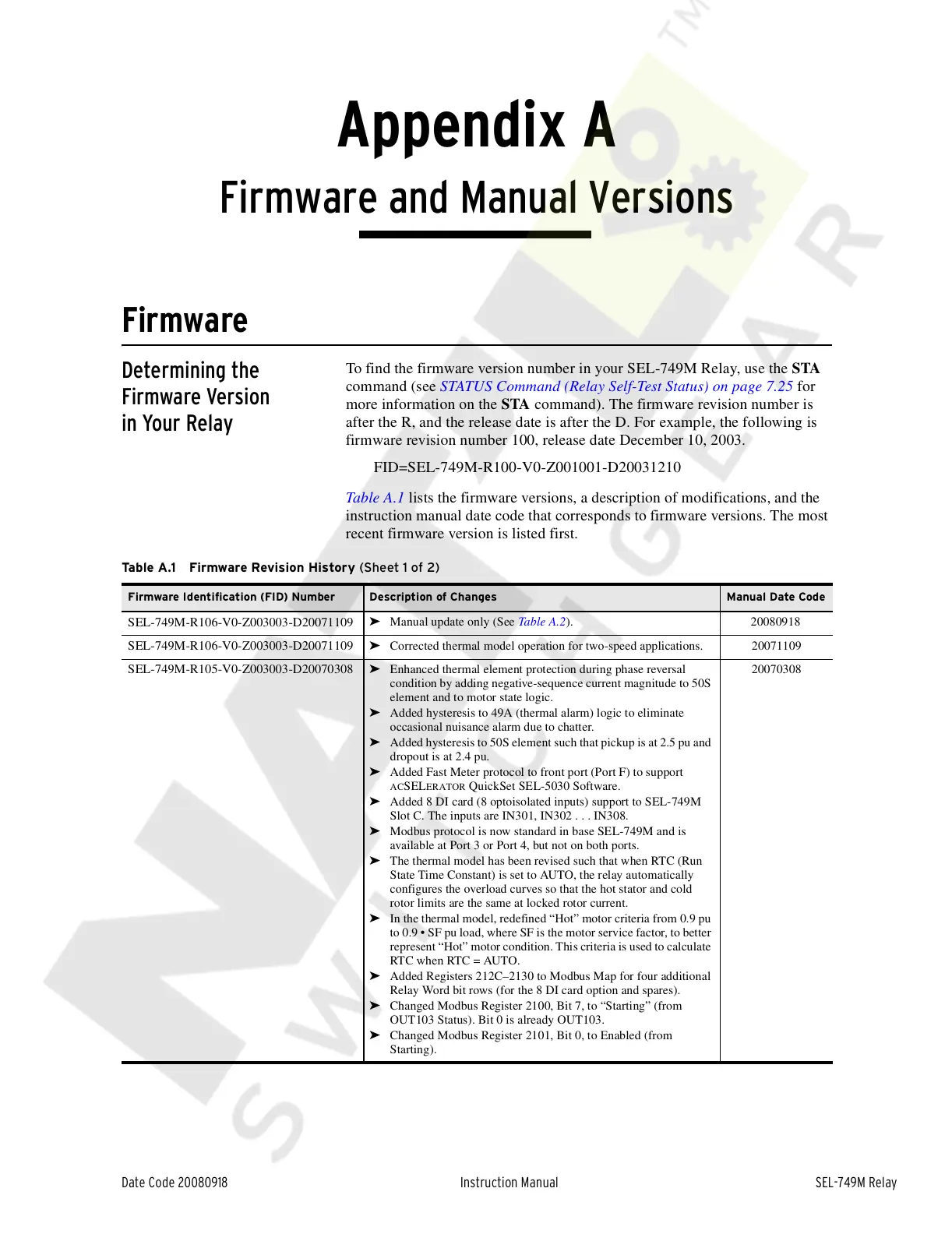
To find the firmware version number in your SEL-749M Relay, use the STA
command (see STATUS Command (Relay Self-Test Status) on page 7.25 for
more information on the STA command). The firmware revision number is
after the R, and the release date is after the D. For example, the following is
firmware revision number 100, release date December 10, 2003.
FID=SEL-749M-R100-V0-Z001001-D20031210
Table A.1 lists the firmware versions, a description of modifications, and the
instruction manual date code that corresponds to firmware versions. The most
recent firmware version is listed first.
Table A.1 Firmware Revision History (Sheet 1 of 2)
Firmware Identification (FID) Number Description of Changes Manual Date Code
SEL-749M-R106-V0-Z003003-D20071109
➤ Manual update only (See Table A.2). 20080918
SEL-749M-R106-V0-Z003003-D20071109
➤ Corrected thermal model operation for two-speed applications. 20071109
SEL-749M-R105-V0-Z003003-D20070308
➤ Enhanced thermal element protection during phase reversal
condition by adding negative-sequence current magnitude to 50S
element and to motor state logic.
➤ Added hysteresis to 49A (thermal alarm) logic to eliminate
occasional nuisance alarm due to chatter.
➤ Added hysteresis to 50S element such that pickup is at 2.5 pu and
dropout is at 2.4 pu.
➤ Added Fast Meter protocol to front port (Port F) to support
ACSELERATOR QuickSet SEL-5030 Software.
➤ Added 8 DI card (8 optoisolated inputs) support to SEL-749M
Slot C. The inputs are IN301, IN302 . . . IN308.
➤ Modbus protocol is now standard in base SEL-749M and is
available at Port 3 or Port 4, but not on both ports.
➤ The thermal model has been revised such that when RTC (Run
State Time Constant) is set to AUTO, the relay automatically
configures the overload curves so that the hot stator and cold
rotor limits are the same at locked rotor current.
➤ In the thermal model, redefined “Hot” motor criteria from 0.9 pu
to 0.9 • SF pu load, where SF is the motor service factor, to better
represent “Hot” motor condition. This criteria is used to calculate
RTC when RTC = AUTO.
➤ Added Registers 212C–2130 to Modbus Map for four additional
Relay Word bit rows (for the 8 DI card option and spares).
➤ Changed Modbus Register 2100, Bit 7, to “Starting” (from
OUT103 Status). Bit 0 is already OUT103.
➤ Changed Modbus Register 2101, Bit 0, to Enabled (from
Starting).
20070308
Courtesy of NationalSwitchgear.com