2.17
Date Code 20080918 Instruction Manual SEL-749M Relay
Installation
AC/DC Control Connection Diagrams
Star-Delta Starting
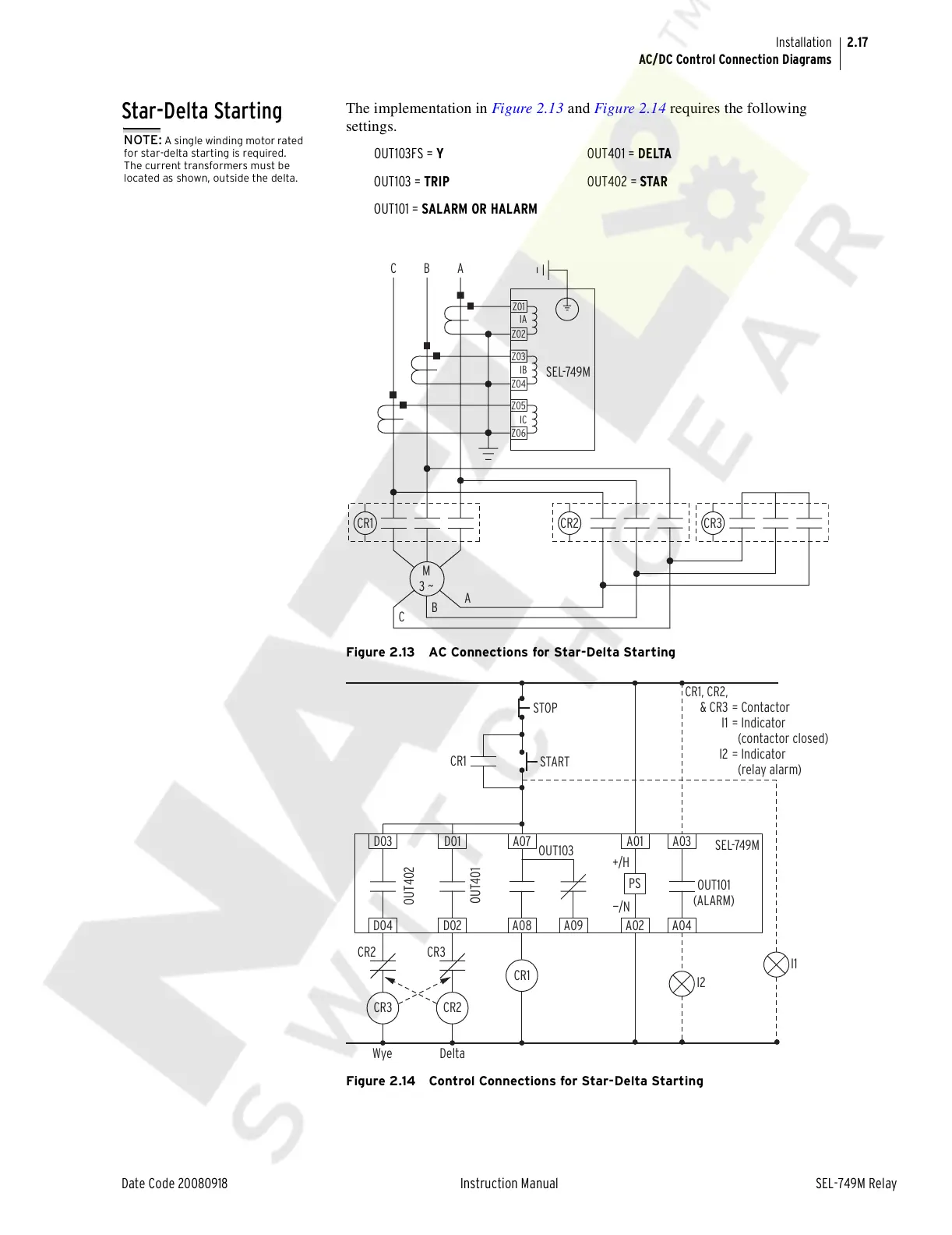
The implementation in Figure 2.13 and Figure 2.14 requires the following
settings.
Figure 2.13 AC Connections for Star-Delta Starting
Figure 2.14 Control Connections for Star-Delta Starting
NOTE: A single winding motor rated
for star-delta starting is required.
The current transformers must be
located as shown, outside the delta.
OUT103FS = Y OUT401 = DELTA
OUT103 = TRIP OUT402 = STAR
OUT101 = SALARM OR HALARM
SEL-749M
A
B
C
ABC
IC
IB
IA
M
3 ~
Z03
Z06
Z05
Z04
Z02
Z01
CR1 CR2 CR3
= Contactor
= Indicator
(contactor closed)
= Indicator
(relay alarm)
CR1, CR2,
& CR3
I1
I2
CR1
STOP
START
I1
OUT103
SEL-749M
OUT101
(ALARM)
OUT402
OUT401
+/H
—/N
A01 A03
A09
PS
A02 A04
A07
A08
CR1
D01
D02
CR2
D03
D04
CR3
CR3
CR2
I2
Delta
Wye
Courtesy of NationalSwitchgear.com