4.26
SEL-749M Relay Instruction Manual Date Code 20080918
Protection and Logic Functions
Voltage-Based Protection
VAR Function
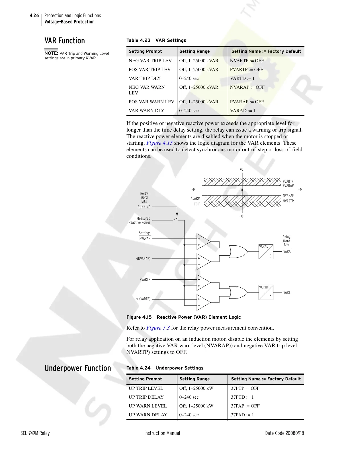
If the positive or negative reactive power exceeds the appropriate level for
longer than the time delay setting, the relay can issue a warning or trip signal.
The reactive power elements are disabled when the motor is stopped or
starting. Figure 4.15 shows the logic diagram for the VAR elements. These
elements can be used to detect synchronous motor out-of-step or loss-of-field
conditions.
Figure 4.15 Reactive Power (VAR) Element Logic
Refer to Figure 5.3 for the relay power measurement convention.
For relay application on an induction motor, disable the elements by setting
both the negative VAR warn level (NVARAP)) and negative VAR trip level
NVARTP) settings to OFF.
Underpower Function
Table 4.23 VAR Settings
Setting Prompt Setting Range Setting Name := Factory Default
NEG VAR TRIP LEV Off, 1–25000 kVAR NVARTP := OFF
POS VAR TRIP LEV Off, 1–25000 kVAR PVARTP := OFF
VAR TRIP DLY 0–240 sec VARTD := 1
NEG VAR WARN
LEV
Off, 1–25000 kVAR NVARAP := OFF
POS VAR WARN LEV Off, 1–25000 kVAR PVARAP := OFF
VAR WARN DLY 0–240 sec VARAD := 1
NOTE: VAR Trip and Warning Level
settings are in primary KVAR.
RUNNING
PVARTP
–(NVARTP)
Measured
Reactive Power
PVARAP
–(NVARAP)
VARA
VARAD
0
VART
VARTD
0
+Q
–Q
–P +P
PVARTP
PVARAP
NVARAP
NVARTP
ALARM
TRIP
Relay
Word
Bits
Relay
Word
Bits
Settings
Table 4.24 Underpower Settings
Setting Prompt Setting Range Setting Name := Factory Default
UP TRIP LEVEL Off, 1–25000 kW 37PTP := OFF
UP TRIP DELAY 0–240 sec 37PTD := 1
UP WARN LEVEL Off, 1–25000 kW 37PAP := OFF
UP WARN DELAY 0–240 sec 37PAD := 1
Courtesy of NationalSwitchgear.com