4.49
Date Code 20080918 Instruction Manual SEL-749M Relay
Protection and Logic Functions
Logic Functions
If setting SETn asserts to logical 1, latch bit LTn asserts to logical 1. If setting
RSTn asserts to logical 1, latch bit LTn deasserts to logical 0. If both settings
SETn and RSTn assert to logical 1, setting RSTn has priority and latch bit LTn
deasserts to logical 0.
Latch Bits: Nonvolatile State
Power Loss
The states of the latch bits (LT01–LT08) are retained if power to the relay is
lost and then restored. If a latch bit is asserted (e.g., LT02 := logical 1) when
power is lost, it is asserted (LT02 := logical 1) when power is restored. If a
latch bit is deasserted (e.g., LT03 := logical 0) when power is lost, it is
deasserted (LT03 := logical 0) when power is restored.
Settings Change
If individual settings are changed the states of the latch bits (Relay Word bits
LT01 through LT08) are retained, as in the preceding Power Loss explanation.
If the individual settings change causes a change in SEL
OGIC control equation
settings SETn or RSTn (n = 1 through 08), the retained states of the latch bits
can be changed, subject to the newly enabled settings SETn or RSTn.
Make Latch Control Switch Settings With Care
The latch bit states are stored in nonvolatile memory so they can be retained
during power loss or settings change. The nonvolatile memory is rated for a
finite number of writes for all cumulative latch bit state changes. Exceeding
the limit can result in an EEPROM self-test failure. An average of 70
cumulative latch bit state changes per day can be made for a 25-year
relay service life.
Settings SETn and RSTn cannot result in continuous cyclical operation of
latch bit LTn. Use timers to qualify conditions set in settings SETn and RSTn.
If you use any optoisolated inputs in settings SETn and RSTn, the inputs each
have a separate debounce timer that can help in providing the necessary time
qualification.
SELOGIC Control
Equation Variables/
Timers
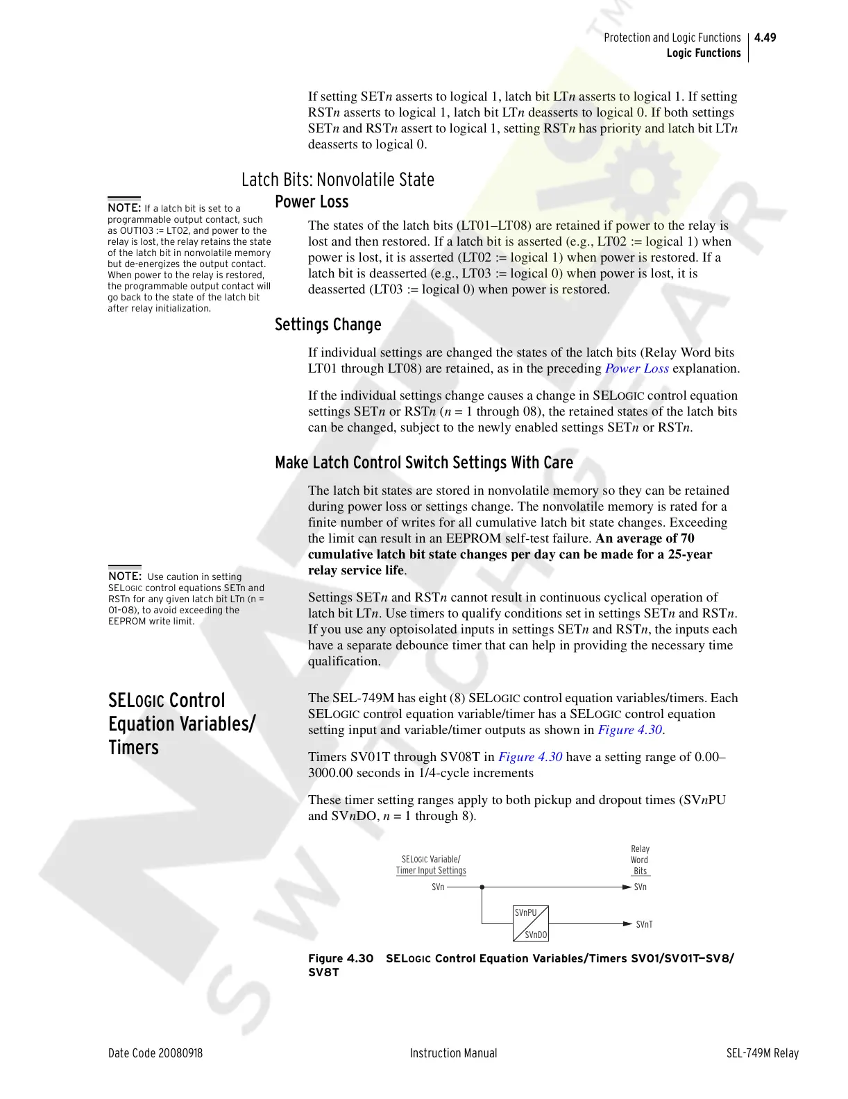
The SEL-749M has eight (8) SELOGIC control equation variables/timers. Each
SEL
OGIC control equation variable/timer has a SELOGIC control equation
setting input and variable/timer outputs as shown in Figure 4.30.
Timers SV01T through SV08T in Figure 4.30 have a setting range of 0.00–
3000.00 seconds in 1/4-cycle increments
These timer setting ranges apply to both pickup and dropout times (SVnPU
and SVnDO, n = 1 through 8).
Figure 4.30 SELOGIC Control Equation Variables/Timers SV01/SV01T—SV8/
SV8T
NOTE: If a latch bit is set to a
programmable output contact, such
as OUT103 := LT02, and power to the
relay is lost, the relay retains the state
of the latch bit in nonvolatile memory
but de-energizes the output contact.
When power to the relay is restored,
the programmable output contact will
go back to the state of the latch bit
after relay initialization.
NOTE: Use caution in setting
SEL
OGIC control equations SETn and
RSTn for any given latch bit LTn (n =
01–08), to avoid exceeding the
EEPROM write limit.
SVn
SVn
SVnT
SEL
OGIC
Variable/
Timer Input Settings
Relay
Word
Bits
SVnPU
SVnDO
Courtesy of NationalSwitchgear.com