Section 08 PROPULSION SYSTEM
Sub-Section 03 (DRIVE SYSTEM)
08-03-12
All Models
5,6, Floating Ring and O-ring
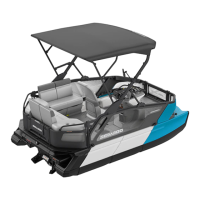
Position the O-ring
no. 6
of the drive shaft in the
flange of the floating ring
no. 5
.
1. O-ring
2. Floating ring
Position the floating ring
no. 5
between the car-
bon ring
no. 10
and the PTO flywheel (seal carrier
for the HX and XP models).
TYPICAL
1. Floating ring
All Models Except the XP and HX
3, Drive Shaft
Install drive shaft.
Engage drive shaft splines in PTO flywheel. Ro-
tate shaft to properly index splines. Make sure
boot is well positioned over shaft end.
XP and HX Models Only
4, Rear Drive Shaft
Install rear drive shaft.
Engage drive shaft splines in coupler
no. 20
. Ro-
tate shaft to properly index splines.
All Models
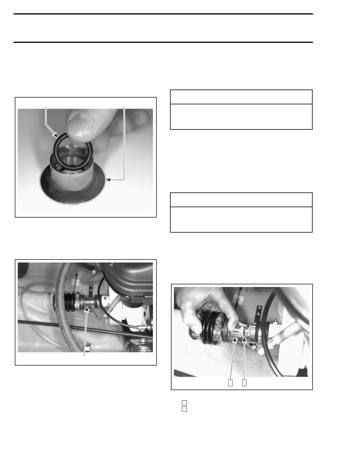
Push the floating ring to compress the boot. Insert
the O-ring in the drive shaft groove.
TYPICAL
Step : Push floating ring
Step : Insert O-ring in the groove
Slide the floating ring onto the O-ring.
F01I0DA
1
2
F02I03A
1
-
CAUTION
Take care not to break the O-ring in the float-
ing ring flange while inserting the drive
shaft.
-
CAUTION
Take care not to break the O-ring in the float-
ing ring flange while inserting the drive
shaft.
F02I04A
1 2
1
2
 Loading...