Distance and angle measurement
9-60
9
Go to page 9·64
· You can switch between displaying all the headings together and displaying each one separately using the
ESC key.
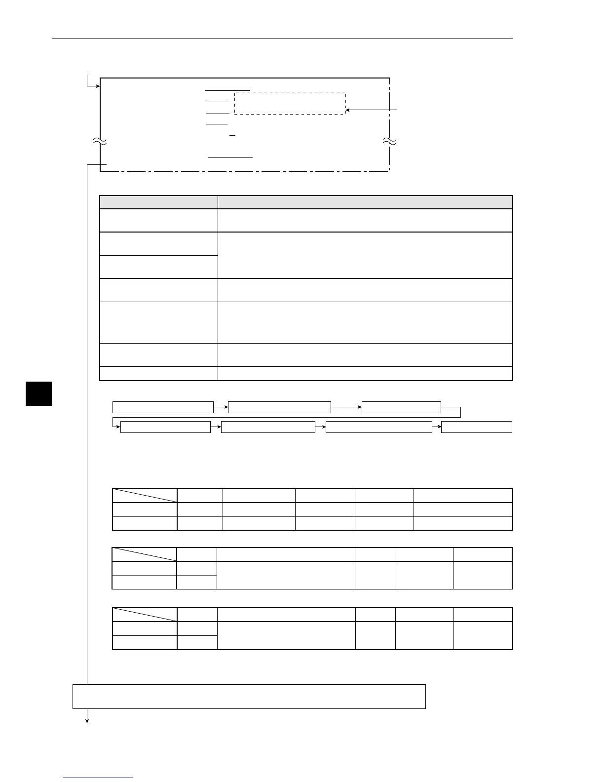
1
MEAS WINDOW
RECTANGLE
X-LINE Y-LINE
2
REF IMAGE
MOVE UP.L(224,208) LO.R(287,271) REG. DISP
3
SEARCH AREA
MOVE UP.L(
216,200)
LO.R(
295,279)
4
DTECT COORD CNTR FREE(256,240)
5
CONTR. PIXEL 1 2 3
q
DETECT ACCURANCY STANDARD HI-PRC
w
UPPER MENU
Return to the [MEASURING COND] (measurement condition) menu and select item
4 AUX.CONDITIONS (auxiliary condition).
This is how the display looks
when the 1MEASURE
WINDOW (measurement
window) is a RECTANGLE
(rectangle).
When either a horizontal or a vertical line is selected please bear the following in mind.
The reference image must be shorter than the search area.
From the previous page: When the GRAY-SEARCH (gray scale search) starting point mode is selected as
the START POINT COND (starting point condition).
[The setting sequence of the starting point conditions in a gray scale search.]
1MEASURE WINDOW
3SEARCH AREA
2REFFERENCE IMAGE
4
DETECTED COORD
5CONTRACT PIXELS qDETECT ACCURANCY
w
UPPER MENU
[Information about the recording of a reference image]
In order to record a reference image it is necessary to freeze the frame.
The specifications for the windows are as follows.
· In the case of a rectangular window
· In the case of a horizontal line
· In the case of a vertical line
Menu
1MEASURE WINDOW
(measurement window)
2REFERENCE IMAGE
3SEARCH AREA
4DETECTED COORD
(detection coordinates)
5CONTRACT PIXELS
(pixel contraction)
qDETECT ACCURANCY
(artifact processing)
wUPPER MENU
Setting details
Select the shape of the measurement window.
Record a reference image and then set the search area.
· If X-LINE (horizontal line) or Y-LINE (vertical line) are selected, then
the UP.L (upper left) and LO.R ( lower right) choices in the screen
above will be ST-PNT (starting point) and E-PNT (end point).
Set the position of the cursor inside the measurement window.
· If FREE is selected, then the cursor may be positioned as desired.
Set the number of pixel contractions.
-See page 9·6 gray scale processing using shared settings.
· When either a X-LINE (horizontal) or a Y-LINE (vertical) are selected
in item 1, the choices here will be 1 or 2.
Select the level of precision used for detection.
-See page 9·6 gray scale processing using shared setting.
This will return you to the [MEASURING COND] menu.
Reference image
Search area
Line type
Solid line
Dotted line
Movement
Units of 4 pixels
Units of 4 pixels
Size
Units of 4 pixels
Units of 4 pixels
Minimum
32×32 (pixels)
32×32 (pixels)
Maximum
X × Y (X × Y=65536 pixels)
512 × 480 pixels
Reference image
Search area
Line type
Solid line
Dotted line
Movement
In a horizontal direction: units of 4 pixels
In a vertical direction: units of 1 pixel
Length
Units of 4
pixels
Minimum length
8 pixels
Maximum length
512 pixels
Reference image
Search area
Line type
Solid line
Dotted line
Movement
In a horizontal direction: units of 1 pixel
In a vertical direction: units of 4 pixels
Length
Units of 4
pixels
Minimum length
8 pixels
Maximum length
480 pixels