9-80
Lead inspection
9
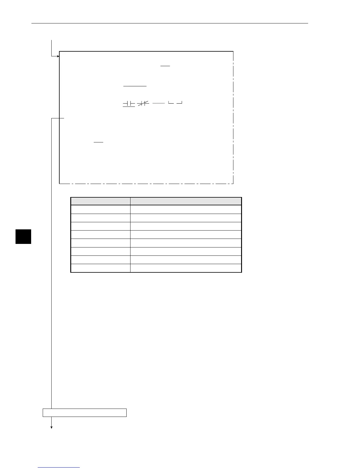
· The input signals which may be set depend on the selection at item 3 as follows.
· For more information on output conditions see the "PC Function," in Chapter 10.
Continued from the previous page
Continued on the following page
Return to the MAIN OPS MENU
DEL.
[OUTPUT CONDITIONS]
(TYPE00-MEAS.1-INSPECT LEAD)
1PAGE NO.
0(0~4) REG.NO YES
2SET POSITION
MOVE
3INPUT SIGNAL
REGT.NO.0(0〜3)
MATCH.M CRD-X CRD-Y
DST D0(0~7) QTY K0(0~7) L-LEN L0(0~7)
CAL N00(0~15) AUXRLY C000(0~127)
4LOGICAL SYMBOL
5OUTPUT SIGNAL
AUX.RLYC000(0~127) DEL.
6UPPER MENU
[PAGE0]
INPUT0
LOGIC
INPUT1
LOGIC
INPUT2
LOGIC
INPUT3
LOGIC
10 234567OUT
The numbers ranging from 0 to 3 in front of the characters are registration numbers.
The numbers ranging from 0 to 7 after the characters are numbers for the object to be mesured.
Selection of 3
Degree of match M
Coordinate X
Coordinate Y
Distance D
Number of objects K
Lead length L
Calculation N
Secondary relay C
Input signals
0M to 3M
0X to 3X
0Y to 3Y
0D0 to 3C7
0K0 to 3K7
0L0 to 3L7
N00 to N15
C000 to C12