9-113
9
Existence inspection by point measurement
Selection of item 3
Point number
Auxiliary rely
P000 to P255
C000 to C127
*
*When AV-LIGHT-LEVEL (average light level) is selected for the processing mode,
the setting range is P000 to P127.
· Items 2 to 5 will be displayed when item 1 is set to YES.
· The input signals which maybe set depend on the selection made in item 3 as follows:
From page 9·111: When BIN-CONV (binary) was selected for the processing mode.
Continued from the previous page: When AV-LIGHT-LEVEL (average light level) is selected
for the processing mode.
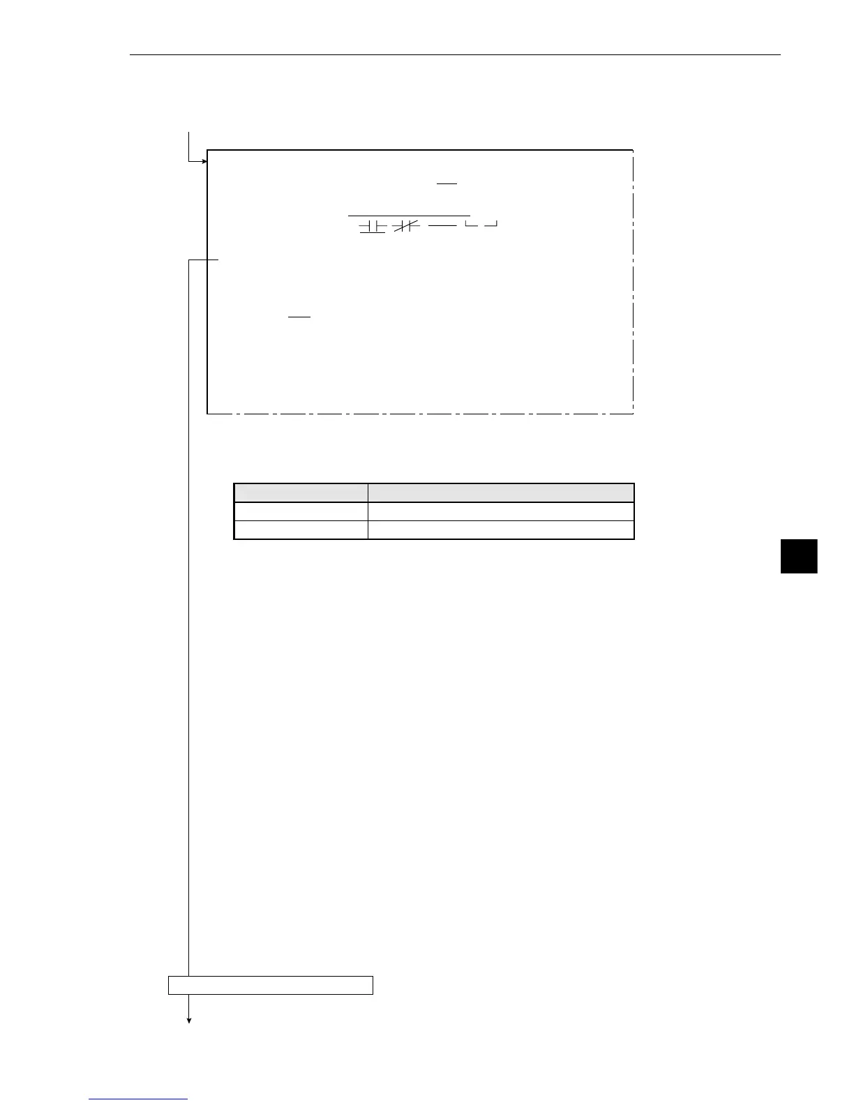
DEL.
[OUTPUT CONDITIONS]
(TYPE00-MEAS.1-POINT MEAS)
1
PAGENO. 0(0~4) REG.NO YES
2
SET POSITION MOVE
3
INPUT SIGNAL POINT NO.000 (0~255) AUXRLY C000 (0~127)
4
LOGICAL SYMBOL
5
OUTPUTSIGNAL AUX.RLYC000 (0~127) DEL.
6
UPPER MENU
[PAGE0]
INPUT0
LOGIC
INPUT1
LOGIC
INPUT2
LOGIC
INPUT3
LOGIC
10 234567OUT
Returns to the MAIN OPS MENU.
Continued on the following page
· For more information on output conditions, see the “PC Function” in Chapter 10.
Input signals