Response time of path1
T
able 109: Example for the calculation of the response time of path1 of a Flexi Soft system
1. Inputs Response time of the
in
put under consideration on
path1
E1 20.5 ms
2. Logic Logic response time 2 × logic execution time 8.0 ms
Delay due to logic application –
3. Outputs Response time of the out‐
put under consider
ation on
path1
A1 44.5 ms
Total response time of path 1 73.0 ms
Input from an EFI-enabled device (E2)
T
able 110: Example for the calculation of the response time for the input from an EFI-enabled
device (E2)
If EFI functions are used via EFI-ena‐
bled de
vices
Response time of the EFI data source
(C4000 receiver (stand-alone))
12.0 ms
Constant (C4000) 1.5 ms
Total E2 13.5 ms
Digital outputs (A1) on path 2
T
able 111: Example for the calculation of the response time for the digital outputs (A1) on path 2
General information Robot response time 40.0 ms
General information Output processing time 4.5 ms
Total A1 44.5 ms
Response time of path2
T
able 112: Example for the calculation of the response time of path2 of a Flexi Soft system
1. Inputs Response time of the
in
put under consideration on
path2
E2 13.5 ms
2. Logic Logic response time 2 × logic execution time 8.0 ms
Delay due to logic application –
3. Outputs Response time of the out‐
put under consider
ation on
path2
A1 44.5 ms
Total response time of path2 66.0 ms
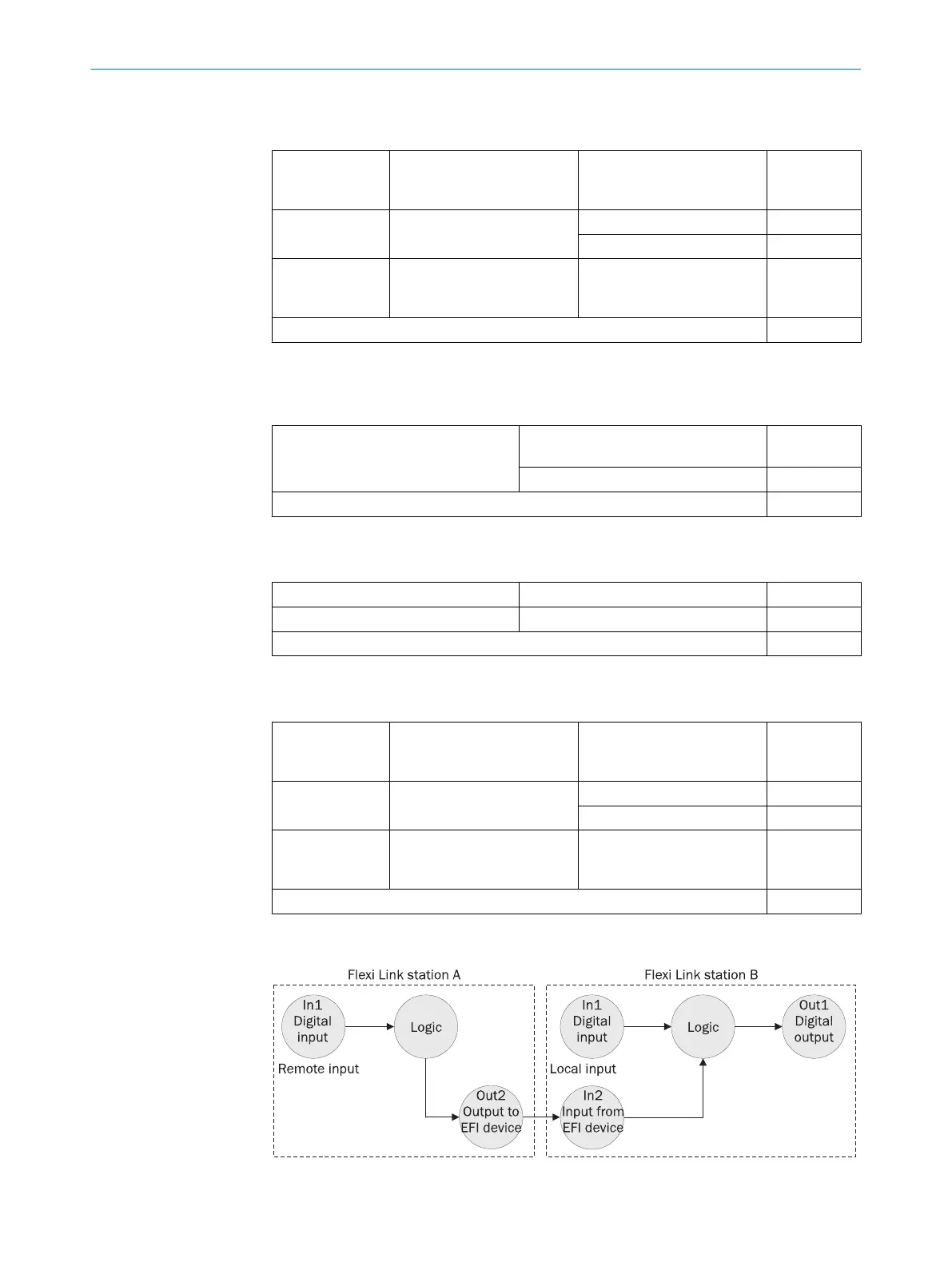
12.2.1.2 Example 2: Calculation of the response time for a Flexi Link system
Figure 67: Response times within a Flexi Link system
TECHNICAL DATA 12
8012478/1IG6/2023-02-24 | SICK O P E R A T I N G I N S T R U C T I O N S | Flexi Soft Modular Safety Controller
137
Subject to change without notice