Interfaces
T
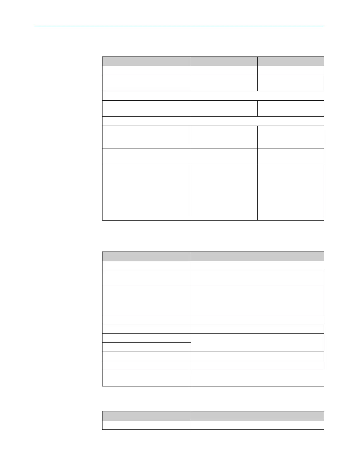
able 121: Interfaces FX3-CPU0, FX3-CPU1, FX3-CPU2 and FX3-CPU3
FX3-CPU0 FX3-CPU1/2/3
Number of EFI interfaces 0 2
Number of Flexi-Line interfaces 0 FX3-CPU1/2: 0
FX3-
CPU3: 1
Data interface Internal bus (FLEXBUS+)
Configuration interface RS-232 FX3-CPU1/2: RS-232
FX3-
CPU3: RS-232, USB
Connection technology RS-232 M8, 4-pin
Connection technology USB
–
FX3-CPU1/2: -
FX3-
CPU3: USB Mini-B,
5-pin
EFI and Flexi Line connection tech‐
nolo
gy
–
Dual level spring terminals
EFI and Flexi Line conductor cross
sec
tion
–
Single-wire or fine-stranded
wire: 0.2 … 1.5mm²
Stranded wire with ferrule:
a) With plastic ferrule max.
0.75mm²
b) Without plastic ferrule
max. 1.5mm²
AWG to UL/CUL: 24 … 16
Electrical data
T
able 122: Power supply unit (A1, A2) for CPU0, CPU1, CPU2 and CPU3 (via system plug MPL0 or
MPL1)
CPU0, CPU1, CPU2, CPU3
Supply voltage 24V DC (16.8V DC … 30V DC)
Supply voltage for UL/CSA applica‐
t
ions
+24V DC
Type of supply voltage PELV or SELV
T
he supply current for the module must be limited exter‐
nally to max. 4A – either by the power supply unit used,
or by means of a fuse.
Short-circuit protection 4A gG (with trigger characteristics B or C)
Overvoltage category II (EN61131-2)
Power consumption Max. 2.5 W
Power loss
Power-up delay Max. 18s
Connection type Screw terminals
Wire cross-section Single-wire or fine-stranded wire: 0.14 … 2.5mm²
A
WG to UL/CUL: 26 … 14
Mechanical data
T
able 123: Mechanical data CPUx
CPU0, CPU1, CPU2, CPU3
Dimensions (W × H × D) 22.5mm × 96.5mm × 120.6mm
12 TECHNICAL DATA
140
O P E R A T I N G I N S T R U C T I O N S | Flexi Soft Modular Safety Controller 8012478/1IG6/2023-02-24 | SICK
Subject to change without notice