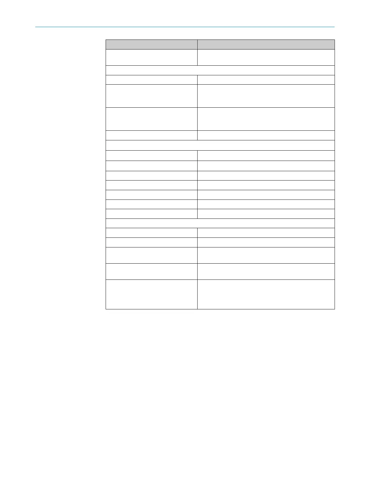
XTIO
Output voltage High 16 … 30VDC (max. 0.8V drop to terminal A1 of this
module)
Leakage current Low
Normal operation Max. 0.1mA
In the event of an error
1)
, H
ard‐
ware version <V1.10 (FX3-XTIO
Step1.xx)
Max. 1.6mA
In the event of an error
1)
, H
ard‐
ware version ≥V1.10 (FX3-XTIO
Step2.xx)
Max. 2.0mA
Output current Max. 2.0A
Sum current I
sum
T
U
≤45°C Max. 4.0A
T
U
≤55°C Max. 3.2A
UL/CSA applications Max. 3.2A
Test pulse duration (test gap)
2)
<650µs or deactivated
Test pulse rate (test period) Min. 200ms
Load capacity ≤0.5µF
Conductor resistance
3)
Max. 5Ω (e.g., 100m × 1.5mm² = 1.2Ω)
Max. permitted coil energy without external protection elements
4)
Hardware version V1.00 0.22J
Hardware version ≥V1.01 0.37J
Response time Depending on the logic configuration, for details see:
see
table 97, page 132
Synchronicity of outputs Qx within a
Flexi Soft station (time delay)
5)
Max. 1ms
Possible switching to High in the
e
vent of an internal hardware error
10ms or 50ms,
Details: see "Fault detection time and fault response
time when using single-channel outputs on the FX3-
XTIO", page 28
1)
In the event of an error (GND line open circuit) and with a load resistance of at least 2.5kΩ, no more than
t
he specified leakage current flows on the safety output. For lower load resistances, the leakage current
may be greater; however, the output voltage will be <5V in this case. A downstream device, for example
a relay or a FPLC (fail-safe programmable logic controller) must detect this state as Low.
2)
When activated, the outputs are tested regularly (brief switching to Low). When selecting the downstream
control elements, ensure that the test pulses with the specified parameters do not result in a switch-off,
or deactivate the test pulses on the outputs yourself.
3)
Make sure to limit the conductor resistance of the individual cables to the downstream controller to this
value in order to ensure that a short-circuit between the outputs is safely detected. (See also EN60204
Electrical equipment of machines, Part 1: General requirements.)
4)
Examples of the maximum resulting coil induction depending on coil current:
•
Hardware version V1.00: 1,760mH @ 0.5A, 440mH @ 1A, 110mH @ 2A
•
Hardware version V1.01: 2,960mH @ 0.5A, 740mH @ 1A, 185mH @ 2A
For inductive loads (e.g. contactors, relays and valves), no external protective elements are required if
this maximum coil energy is not exceeded.
RC elements parallel to the inductive load should not be used because these can create an oscillating
circuit that causes an overshoot in the positive voltage range once the induction voltage has decayed
and thereby trigger a cross-circuit error. The tolerated time for the overshoot (>3.5V) must be
observed:
•
Firmware version ≤V2.10.0: <1ms
•
Firmware version V2.11.0: <3ms
•
Firmware version ≥V3.00.0: <3ms or <43ms if an extended error detection time for switching
capacitive loads has been configured
The overshoot can be reduced if necessary using an external parallel resistance.
12 T
ECHNICAL DATA
144
O P E R A T I N G I N S T R U C T I O N S | Flexi Soft Modular Safety Controller 8012478/1IG6/2023-02-24 | SICK
Subject to change without notice