EasyManuals Logo

SICK Flexi Soft User Manual

SICK Flexi Soft
200 pages
To Next Page IconTo Next Page
To Previous Page IconTo Previous Page
Page #50 background imageLoading...
Page #50 background image
1
3
2
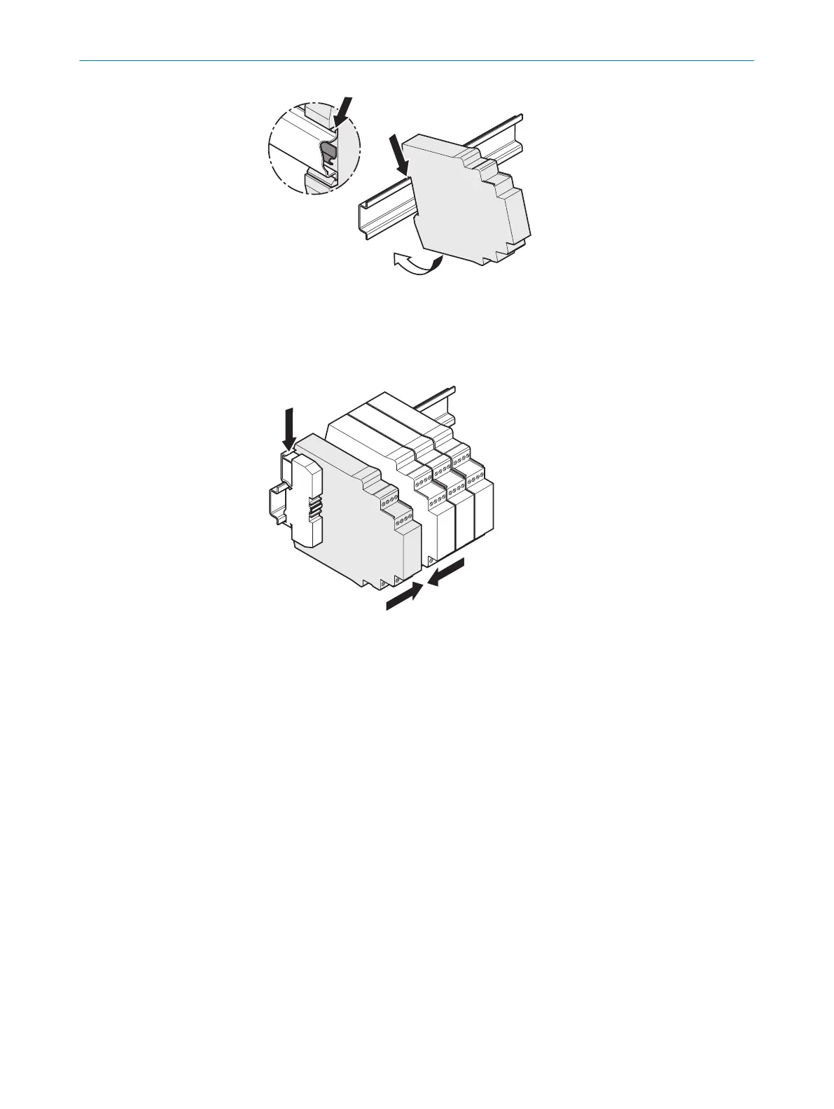
Figure 25: Mounting the module on the DIN mounting rail
4. Slide the modules together one by one (as indicated by the arrows) until the
side
-mounted plug connector engages.
5. Mount the end pieces on the left- and right-hand sides.
Figure 26: Attaching the end pieces
Complementary information
T
he modules are interconnected via a FLEXBUS+ plug connector, which is integrated
into the housing. Before removing a module from the mounting rail, slide the modules
approx. 10mm apart.
4 MOUN
TING
50
O P E R A T I N G I N S T R U C T I O N S | Flexi Soft Modular Safety Controller 8012478/1IG6/2023-02-24 | SICK
Subject to change without notice

Table of Contents

Questions and Answers:

Question and Answer IconNeed help?

Do you have a question about the SICK Flexi Soft and is the answer not in the manual?

SICK Flexi Soft Specifications

General IconGeneral
Safety Integrity Level (SIL)SIL3
Performance Level (PL)PL e
ProgrammingFlexi Soft Designer
Power Supply24 V DC
Safety ProtocolsPROFIsafe, CIP Safety
Protection ClassIP20
Number of I/OsConfigurable
Operating Voltage24 V DC
Power ConsumptionDepends on configuration
Dimensions (W x H x D)Varies depending on the module configuration
WeightVaries depending on the module configuration
Number of Safety InputsConfigurable
Number of Safety OutputsConfigurable
Safety StandardIEC 61508, IEC 62061, ISO 13849
Operating Temperature0°C to +55°C
Response Time< 10 ms (typical)
Storage Temperature Range-25°C to +70°C
Relative Humidity15 % ... 95 %, non-condensing

Related product manuals