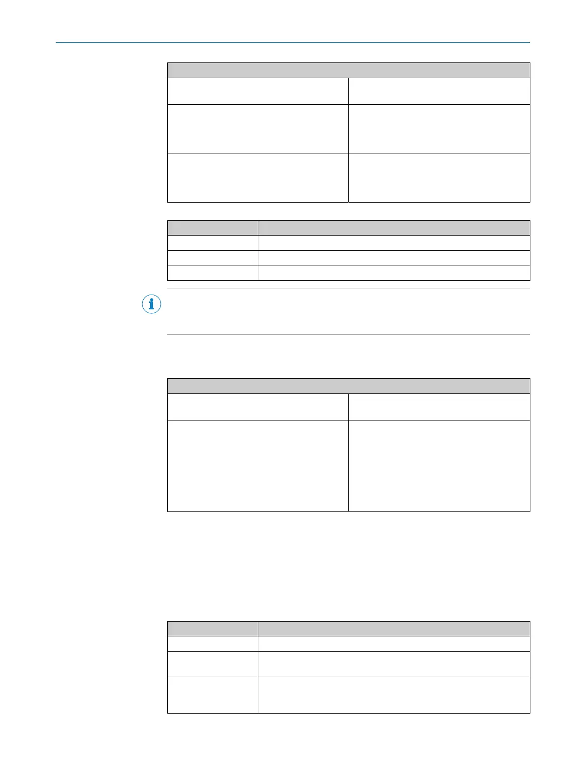
Electrical connection: example with FX3-XTIO
2 positions, at test output Channel 1: contact E31 between X1 and I3
Channe
l 2: contact E41 between X2 and I4
3 positions, at 24 V Channel 1: contact E13 between 24 V and I5
Channe
l 2: contact E23 between 24 V and I6
Channel 3: contact E31 between 24 V and I7
Channel 4: contact E41 between 24 V and I8
3 positions, at test output Channel 1: contact E13 between 24 V and I1
Channe
l 2: contact E23 between 24 V and I2
Channel 3: contact E31 between X1 and I3
Channel 4: contact E41 between X2 and I4
Table 55: Functions with the E100
Function Notes
Tested Possible
Series connection Not possible
Discrepancy time See the report in the configuration software
NOTE
Y
ou will find more information in the operating instructions for the enabling switch
E100.
5.4.1.4 Two-hand control
Table 56: Connection of the two-hand control
Electrical connection: example with FX3-XTIO
Type IIIA, at 24 V Channel 1: contact between 24 V and I1
Channe
l 2: contact between 24 V and I2
Type IIIC, at 24 V Channel 1: left-hand normally open between
24 V and I1
Channe
l 2: left-hand normally closed between
24 V and I2
Channel 3: right-hand normally open between
24 V and I3
Channel 4: right-hand normally closed between
24 V and I4
Type IIIA
W
ith type IIIA, two equivalent inputs (N/O contacts for the 2 two-hand switches) are
monitored.
A valid input signal is only generated if the ON state (High level) is present at both
inputs within a period of 0.5 s (synchronous changeover, both two-hand switches actu‐
ated) and both were previously in the OFF state (Low level).
Table 57: Functions with type IIIA two-hand control
Function Notes
Tested Possible
Series connec‐
t
ion/cascading
Not possible
Discrepancy time Fixed preset value: 500 ms
See f
unction block for type IIIA two-hand in the logic of the main mod‐
ule, with which these outputs are to be evaluated.
5 ELECTRICAL INSTALLATION
80
O P E R A T I N G I N S T R U C T I O N S | Flexi Soft Modular Safety Controller 8012478/1IG6/2023-02-24 | SICK
Subject to change without notice