Project planning
FLOWSIC100 Flare-XT · Operating Instructions · 8023761/V 1-0/2020-10 · © SICK Engineering GmbH 25
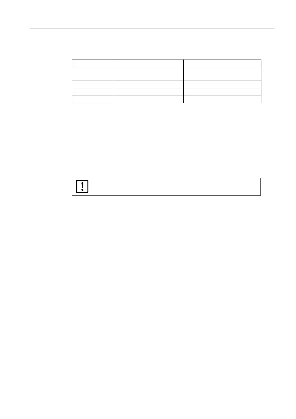
The Table shows for which calculations the use of external pressure and temperature
transmitters is required.
4.2.4 Applications with wet gas
Condensate can accumulate in the nozzle pipes. The following solutions can help to prevent
measurement problems (malfunctions caused by solid-borne noise, see Service Manual),
or damage when removing the sender/receiver unit (condensate runs out).
● Use a nozzle position which prevents accumulations of condensates in nozzle pipes.
● Use a closed continuous or periodical condensate drain with backflow to the pipeline.
● Isolate the nozzle pipe to reduce dew point underruns (only for low gas temperatures
< 100 °C).
4.2.5 Clearance for fitting and removing the sender/receiver units
Calculation of
External pressure transmitter External temperature transmitter
Volumetric flow in
standard condition
x x
Mass flow
x x
Molecular weight
— x
Reynolds number
x x
NOTICE:
Observe the dimension drawings in
p. 167, §12.8.1.