130 FLOWSIC100 Flare-XT · Operating Instructions · 8023761/V 1-0/2020-10 · © SICK Engineering GmbH
Commissioning FLOWSIC100 Flare-XT
Table 16 Selection options
● Invert logic: Inverts the logic of the received signal
● Raw read: Instantaneous value, without debounce
● Debounce: Debounce time (the time a digital input must be constant without status
change)
● Alarm on error: In case of an error of the digital input, an error is displayed in the system
status of the FLOWSIC100 Flare-XT
● Test mode:
– Off: Test mode not active
– Permanently on: Test of digital input, permanently on
– Permanently off: Test of digital input, permanently off
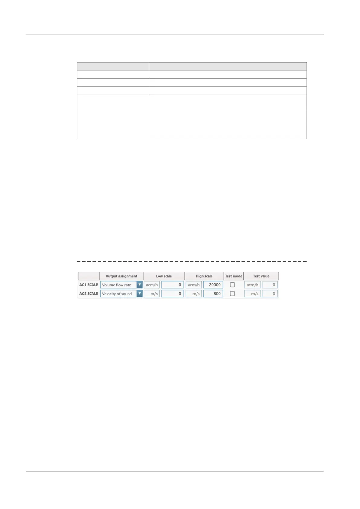
7.5.6.4 AI/AO
▸
Determine the output values for the analog outputs.
▸
Determine whether an alarm is to be displayed for analog input errors.
Fig. 82 Output via analog output (example)
● Lower output value: Minimum output value of the analog output
● Upper output value: Maximum output value of the analog output
● Test mode: Test mode active
● Test value: Test of the output in relation to the selected upper and lower output value
AO check cycle:
A lower and a higher output value can be set for the check cycle. Both values are output at
the start of the check cycle for the time specified in the “Duration of steps” field.
Selection Description
Maintenance Set maintenance condition
Start check cycle Start check cycle of the sender/receiver units
Start AO check cycle Start check cycle of the analog outputs
Start AO check and check
cycle
Start check cycle of analog outputs and sender/receiver
units
Data valid
Overall status for the measuring point; when the control
system signals an incorrect overall status, the Interface Unit
increments the error counters, even when there is no error
on the FLOWSIC100 Flare-XT