112 FLOWSIC100 Flare-XT · Operating Instructions · 8023761/V 1-0/2020-10 · © SICK Engineering GmbH
Installation Interface Unit
6.5.6
Connection area for field-side wiring
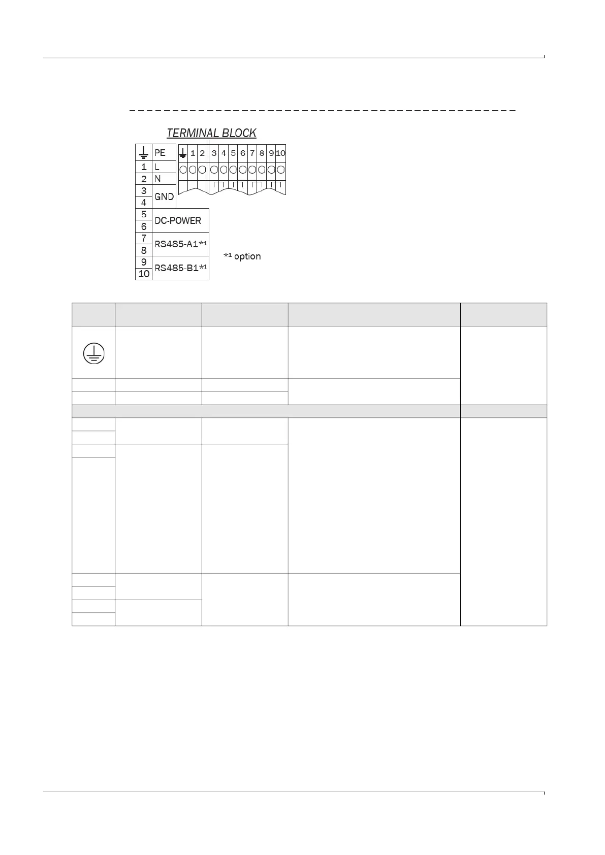
Fig. 66 Terminal blocks
Table 10 Terminal assignment of the terminal blocks
Terminal
No.
Short name Function Comment Conductor size
Ground symbol Grounding Connected with GND 0.5 … 2.5 mm
2
1 L1 Phase conductor Optional - AC variant
2 N Neutral conductor
Separator / partition plate
3 GND Minus pole - DC Variant-dependent wiring
DC variant
– Connection of ext. power supply unit
– Routing of external power supply to
FLSE100-XT sender/receiver units
AC variant:
– Internal 24 VDC power supply unit is
connected
– Connection of external. FLSE100-XT
sender/receiver units for their power supply
GND is connected electrically with the exterior
ground terminal
0.5 … 2.5 mm
2
4
5 DC power Positive pole - DC
6
7 RS485-A1 Serial interface Installation option for connection of two
FLSE100-XT sender/receiver units,
connection from P3 to the terminal blocks
must be made on-site
8
9 RS485-B1
10