138 FLOWSIC100 Flare-XT · Operating Instructions · 8023761/V 1-0/2020-10 · © SICK Engineering GmbH
Operation
8. 1
Operating concept
The Interface Unit display comprises an LCD display for measuring screens and configuring,
4 buttons for menu navigation and an area to attach an infrared/USB adapter (Order No.
6050602) for data communication.
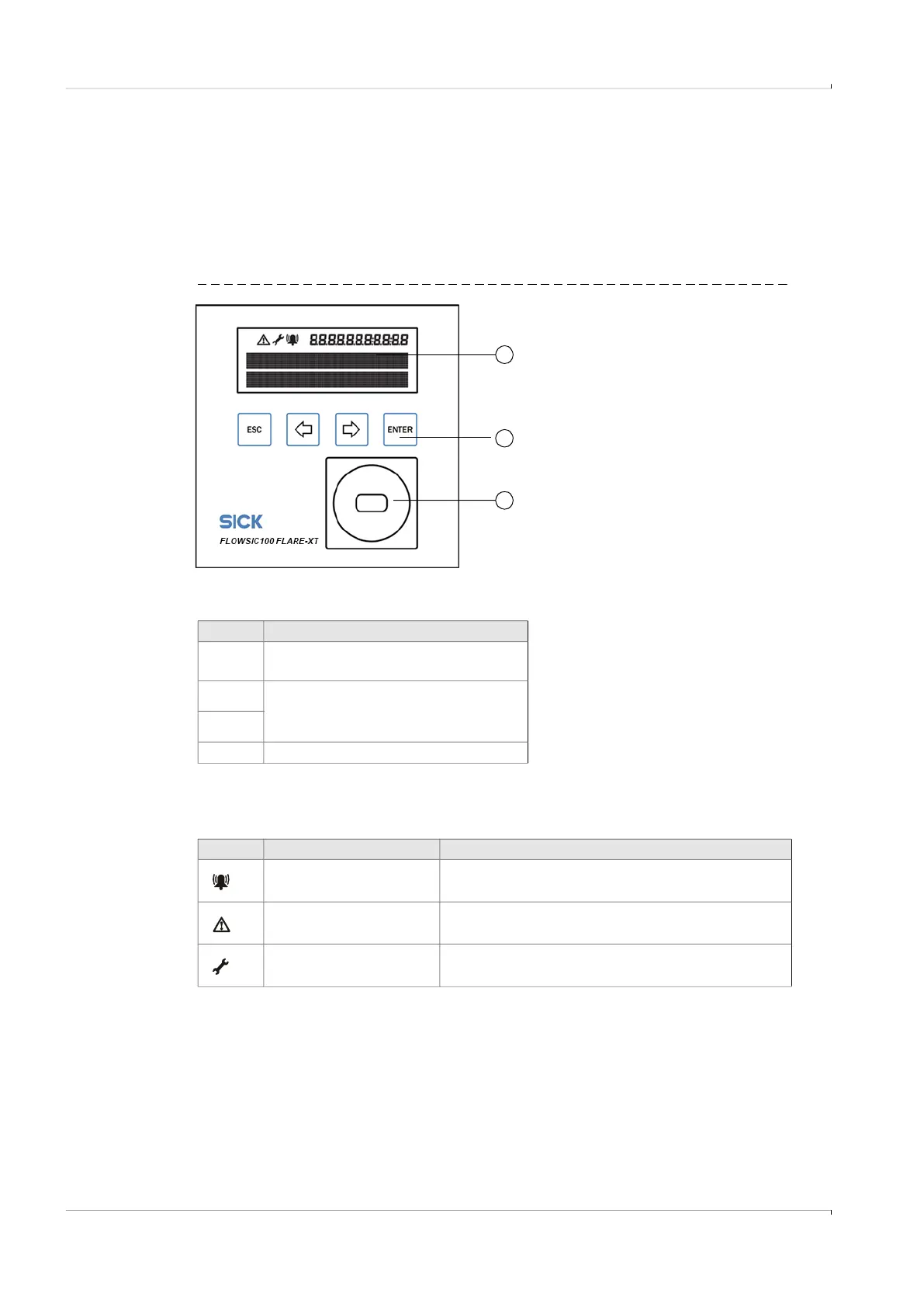
8. 2 Display and operating elements
Fig. 93 Display and operating elements
8. 3
Display in the symbol bar
1
3
2
1 Display
2 Buttons
3 Optical data interface (infrared)
Table 17 Buttons
In menu
Esc
Returns to next higher level of the
operator menu.
Toggles between single menu entries
on one level.
ENTER Calls up a submenu.
Table 18 Symbols
Symbol Significance Description
Device status: Malfunction The device has an error, the measured value is invalid.
Device status: Warning The device has a warning, the measured value is still valid.
Configuration mode Configuration mode is active, parameters can be changed on
the device.