System description
FLOWSIC100 Flare-XT · Operating Instructions · 8023761/V 1-0/2020-10 · © SICK Engineering GmbH 19
3.4
System configuration
FLOWSIC100 Flare-XT is available as 1- or 2-path measuring system. The following Figures
show cross-duct installations (F1F-S, F1F-M, F1F-H). In principle, the configuration also
applies to one-sided installation (F1F-P).
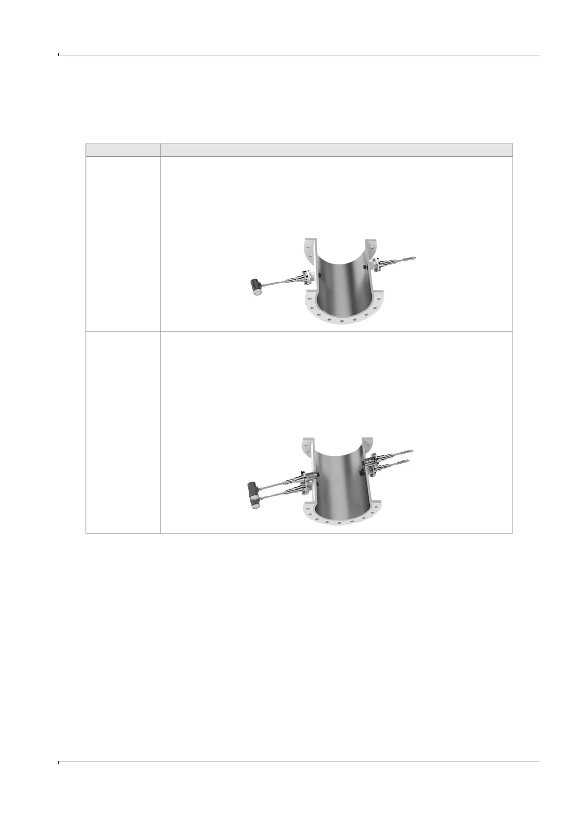
Configuration Description
1-path
measurement
Two sender/receiver units are mounted on the pipeline.
The measuring path is positioned across the center of the pipeline.
Special operating conditions can make it necessary to position the path outside the
pipeline center (shortens the measuring path).
A probe version can also be used instead of two sender/receiver units (type F1F-P).
2-path
measurement
Two pairs of sender/receiver units are installed at the same measuring location and
are connected to the same Interface Unit.
Both measuring paths are positioned outside the center of the pipeline and run
parallel to one another.
The Interface Unit calculates a measuring result from both measuring paths.
2-path measurement is used to achieve higher measurement accuracy or when flow
conditions are complicated.