Technical data
FLOWSIC100 Flare-XT · Operating Instructions · 8023761/V 1-0/2020-10 · © SICK Engineering GmbH 165
12 .7
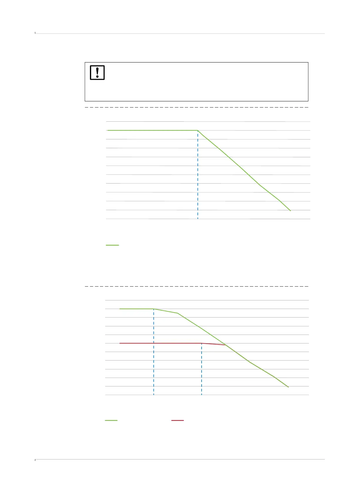
Derating pressure resistance
Fig. 104 F1F-S/-M
Fig. 105 F1F-H
NOTICE:
The diagrams are valid for the standard versions of the sender-/receiver units
FLSE100-XT only. Deviations for other device versions are possible.
The maximum design values stated on the type plates of the devices shall be
respected.
11
12
14
15
16
17
-200 -150 -100 -50 50 100 150
10
Pressure [bar (g)]
Temperature [°C]
200 250
13
0300
18
19
20
21
38 °C
F1F-P (CSA)
F1F-S/-M
Pressure [bar (g)]
Temperature [°C]
11
12
13
14
15
16
-100 -50 0 50 100 200 250
10
Pressure [bar (g)]
Temperature [°C]
17
150 300
18
19
20
21
F1F-H (ATEX) F1F-H (CSA)
0°C
100 °C
F1F-H (ATEX) F1F-H (CSA)
Pressure [bar (g)]
Temperature [°C]