Installation Interface Unit
FLOWSIC100 Flare-XT · Operating Instructions · 8023761/V 1-0/2020-10 · © SICK Engineering GmbH 111
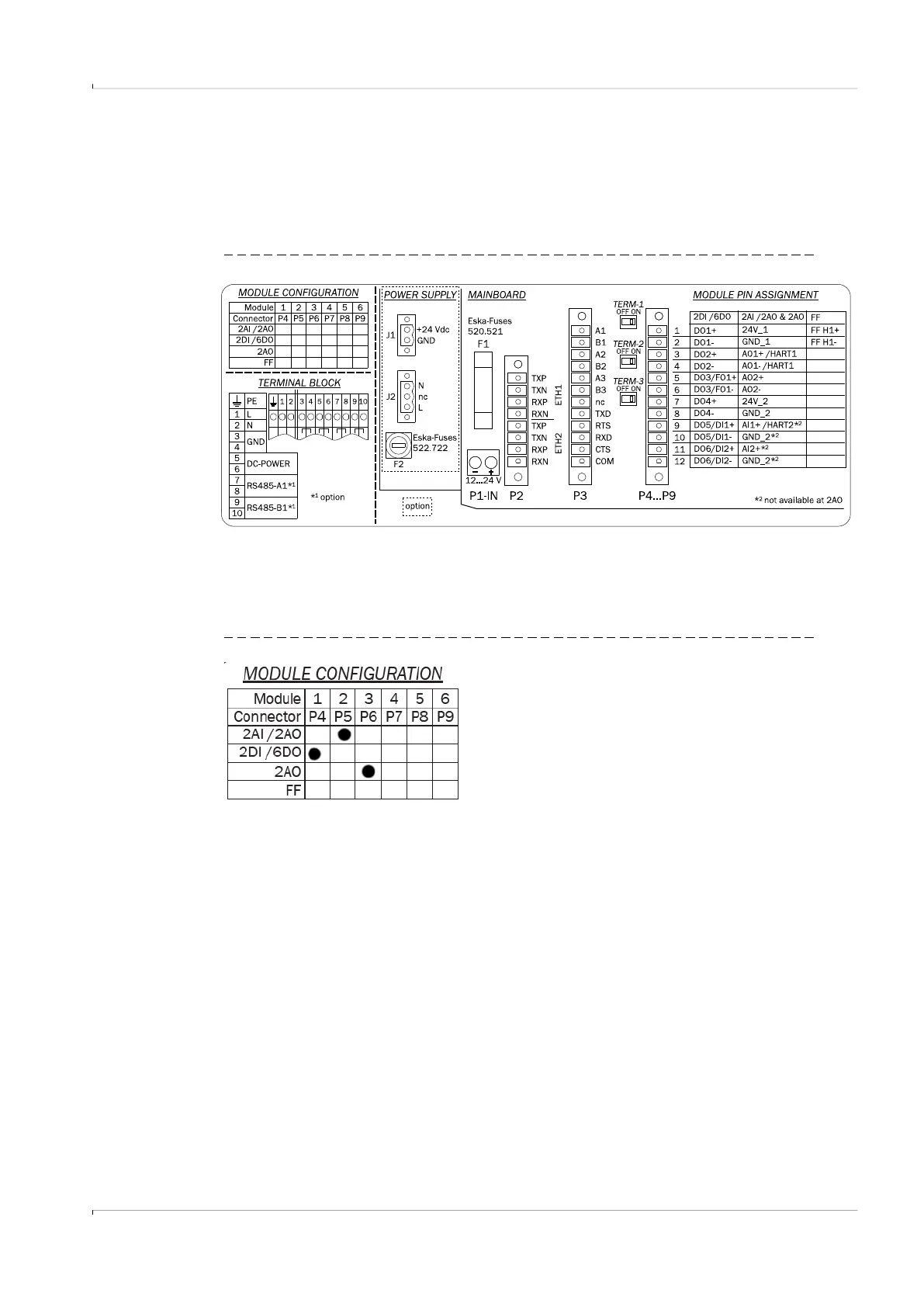
The pin assignment is shown on the sticker on the inside of the door:
● Device module configuration
● Connection area for field-side wiring
● Termination resistors of serial RS485 lines
● Identification of fuses and fuse characteristics
Fig. 64 Terminal assignment
6.5.5.2
Device module configuration
The module configuration of the respective device is marked on the sticker on the inside of
the enclosure door:
Fig. 65 Module configuration (example; the first line designates module slots 1-6)