EasyManuals Logo

SICK FLOWSIC100 Flare-XT User Manual

SICK FLOWSIC100 Flare-XT
188 pages
To Next Page IconTo Next Page
To Previous Page IconTo Previous Page
Page #39 background imageLoading...
Page #39 background image
Installation FLSE100-XT
FLOWSIC100 Flare-XT · Operating Instructions · 8023761/V 1-0/2020-10 · © SICK Engineering GmbH 39
5.3.2
Sender/receiver units
Cross-duct
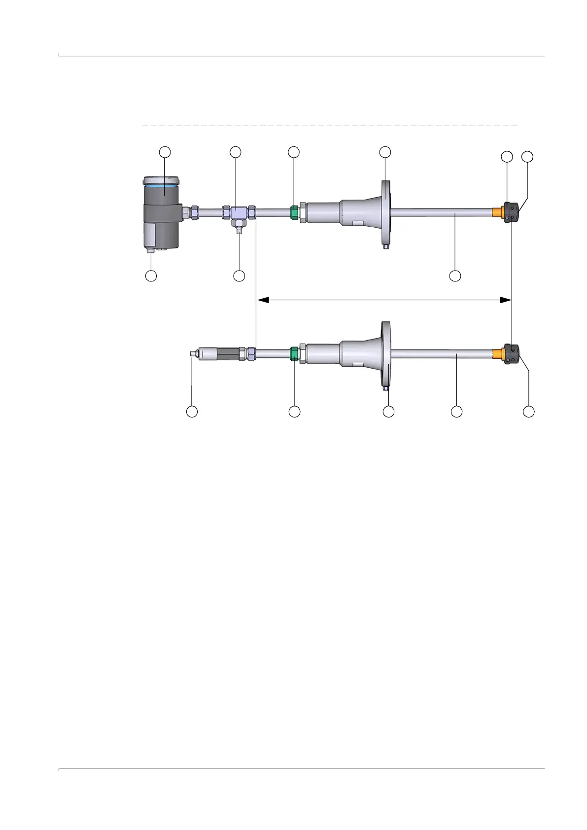
Fig. 10 F1F-S (Master and slave shown as examples)
1 Pressure compensation element 6 Retraction nozzle
2 Electronics unit 7 Duct probe
3 T-connector 8 Sensor contour
4 TNC connector (connection for Slave) 9 Transducer
5 Self-cutting ring 10 TNC connector (connection for Master)
1 7
8
6
4
532
Sensor length
9
8
65
9
7 910

Table of Contents

Questions and Answers:

Question and Answer IconNeed help?

Do you have a question about the SICK FLOWSIC100 Flare-XT and is the answer not in the manual?

SICK FLOWSIC100 Flare-XT Specifications

General IconGeneral
BrandSICK
ModelFLOWSIC100 Flare-XT
CategoryMeasuring Instruments
LanguageEnglish

Related product manuals