114 FLOWSIC100 Flare-XT · Operating Instructions · 8023761/V 1-0/2020-10 · © SICK Engineering GmbH
Installation Interface Unit
6.5.7
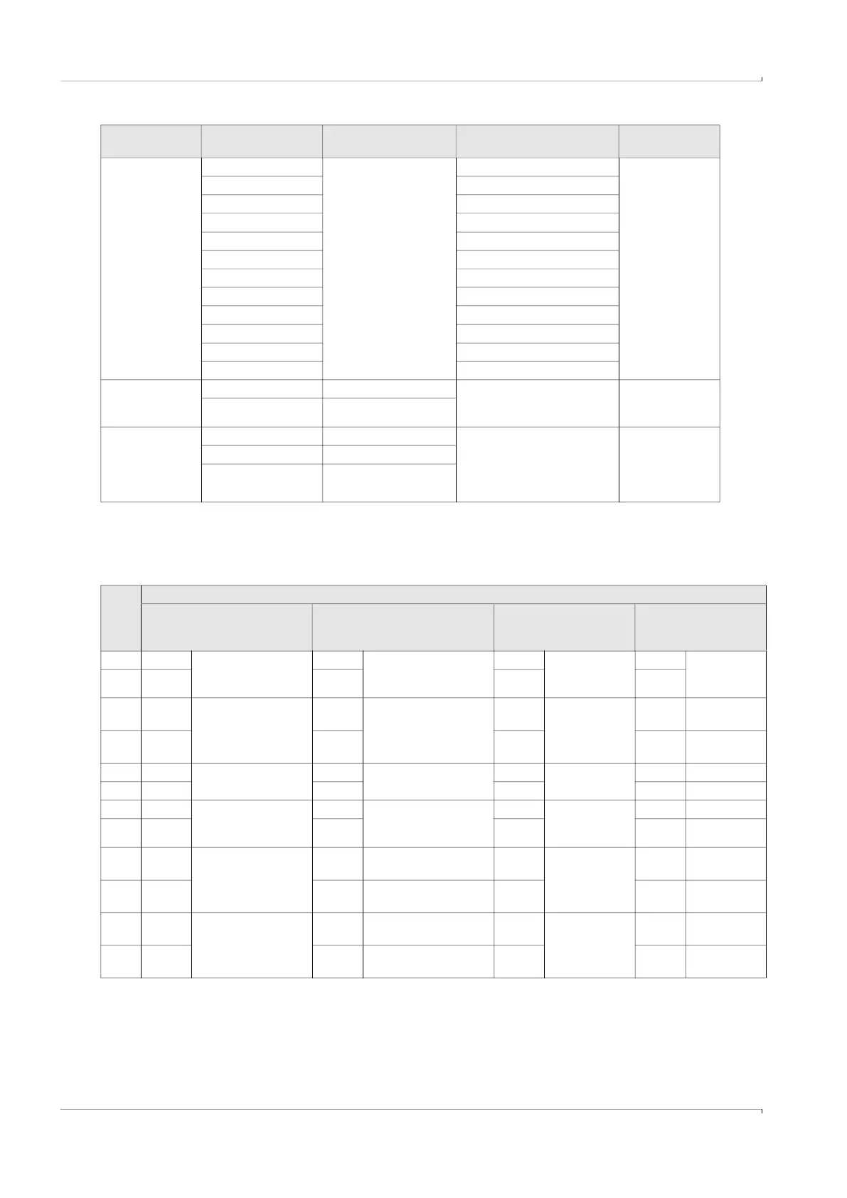
Connection assignment of I/O modules
Table 11 Signal definition of individual modules
P4 to P9 1 Directly connected to
I/O module slots 1 to 6,
example:
P4 connected to slot 1
etc.
Exact pin assignment
depending on the
module, see → Table 11
0.5 … 1.5 mm
2
2
3
4
5
6
7
8
9
10
11
12
J1 +24V DC Positive pole - DC 24V output voltage of internal
power supply unit
*optionally available
0.5 … 2.5 mm
2
GND Minus pole – DC, GND
J2 N Neutral conductor Power supply connection of
internal power supply unit,
prewired to terminal blocks 1
and 2
*optionally available
0.5 … 2.5 mm
2
nc Not connected
L Phase conductor
Plug/terminal
name
Pin identification Function Comment Conductor size
Pin
ident.
I/O module
Analog module type 1
(2AI/2AO)
Analog module type 2
(2AO)
Digital module type 1
(2DI/6DO)
Interface module
FOUNDATION Fieldbus
(FF)
1 24V_1 Auxiliary voltage for
up to two current
loops, max. 60 mA
24V_1 Auxiliary voltage for up
to two current loops,
max. 60 mA
DO1+ Digital output FF H1+ FOUNDATION
Fieldbus
2 GND_1 GND_1 DO1- FF H1-
3 AO1+/
HART1
Analog output;
HART Slave
AO1+/
HART1
Analog output;
HART Slave
DO2+ Digital output
4 AO1-/
HART1
AO1-/
HART1
DO2-
5 AO2+ Analog output AO2+ Analog output DO3+ Digital output
6 AO2- AO2- DO3-
7 24V_2 Auxiliary voltage for
up to two current
loops, max. 60 mA
24V_2 Auxiliary voltage for up
to two current loops,
max. 60 mA
DO4+ Digital output
8 GND_2 GND_2 DO4-
9 AI1+/
HART2
Analog input;
HART master
DO5+/
DI1+
Switching
output/
digital input
10 GND_2 DO5-/
DI1-
11 AI2+ Analog input DO6+/
DI2+
Switching
output/
digital input
12 GND_2 DO6-/
DI2-