Installation Interface Unit
FLOWSIC100 Flare-XT · Operating Instructions · 8023761/V 1-0/2020-10 · © SICK Engineering GmbH 113
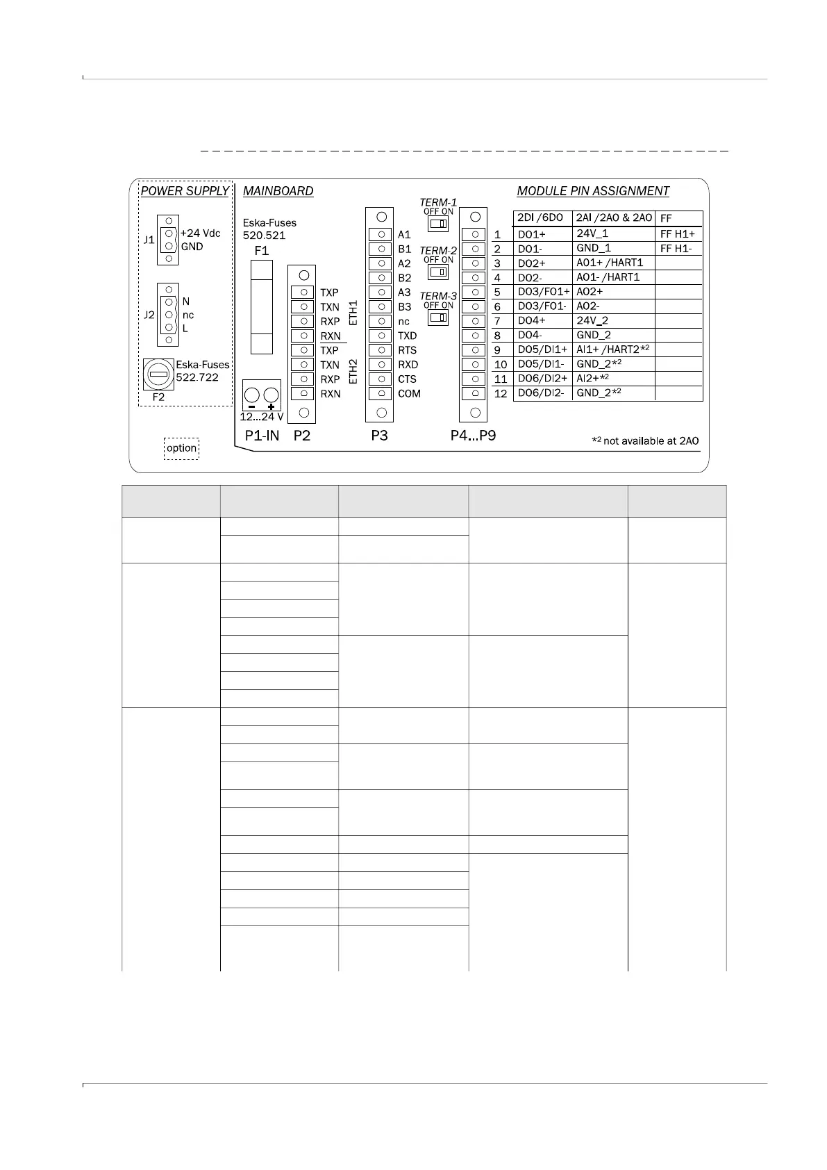
Overview of field connections mainboard and 115 ... 230 VAC power supply
Fig. 67 Field connections
Plug/terminal
name
Pin identification Function Comment Conductor size
P1 1 Minus pole – DC, GND Power supply of electronic
unit, prewired at the factory to
terminal block 3 to 6
0.5 … 1.5 mm
2
2 Positive pole - DC
P2 TXP – ETH1 Data line of first
Ethernet interface
100Base-TX or 10Base-T full
and halfduplex Ethernet
0.14 … 1.5 mm
2
TXN – EHT1
RXP - ETH1
RXP - ETH1
TXP – ETH2 Data line between of
second Ethernet
interface
100Base-TX or 10Base-T full
and halfduplex Ethernet
TXN – EHT2
RXP – ETH2
RXP – ETH2
P3 A1 Serial RS485 internal COM5,
Connection FLSE100-XT
0.5 … 1.5 mm
2
B1
A2 Serial RS485 internal COM2,
Connection Scada, Service PC
or Gas chromatograph
B2
A3 Serial RS485 internal COM3,
Connection Scada, Service PC
or Gas chromatograph
B3
nc Not connected
TXD Transmit data Serial RS232
Internal COM1,
Connection Scada, Service PC
or Gas chromatograph
RTS Request to send
RXD Receive data
CTS Clear to send
COM Common Ground –
connected electrically
with GND