24 FLOWSIC100 Flare-XT · Operating Instructions · 8023761/V 1-0/2020-10 · © SICK Engineering GmbH
Project planning
4.2.2
Additional requirements for optional spool piece
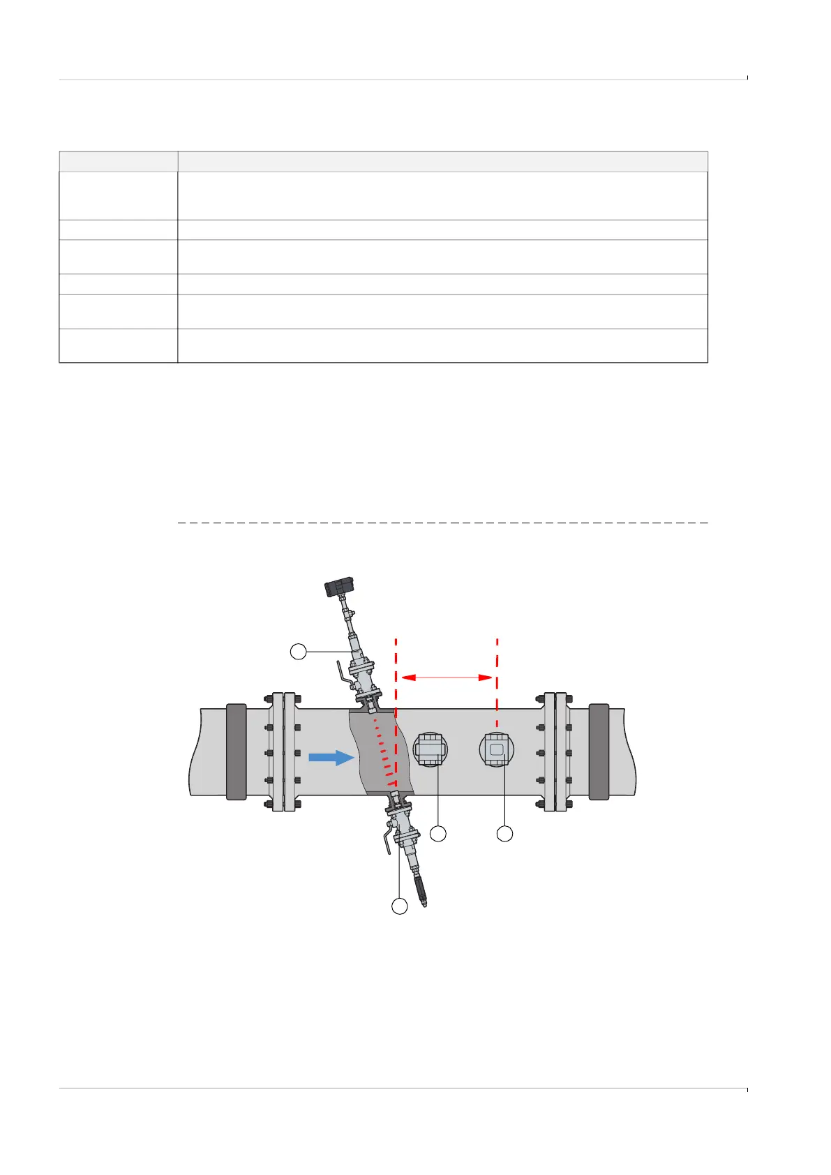
4.2.3 Installation location for external pressure and temperature transmitters (option)
Pressure tappings and thermowells for external transmitters have to be installed in the
following way:
● Pressure tapping connection: Directly at the measuring point, centrally above the
measuring path, on the top of the pipeline
● Thermowell: Outlet section with distance 5 D
T
( = 5 * thermowell diameter), measured
from the middle of the measuring path, on the top of the pipeline
Fig. 5 Installation location
Criteria Requirements
Pipeline design
● Same nominal size of adjacent pipes and spool piece.
● Differences of internal diameters of inlet pipe and spool piece < 1%.
● No welding beads and burs on the flanges of the inlet pipe
Gas flow Free from any foreign material, dust and liquids. Otherwise, filters and traps shall be used.
Seals between spool
piece and pipeline
Must not protrude into the pipeline. Any protrusion into the flowing gas stream may change the flow
profile and thus may adversely affect measuring accuracy.
Pressure sensor Pressure tapping over the measuring path
Temperature sensor
Spool piece with standard installation length with integrated pressure tapping, temperature sensor
5 D
T
( = 5 * diameter of the thermowell) in the outflow area
Fastening and sealing
material
Bolts, nuts and flange seals used must be suitable for the operational conditions and comply with legal
regulations and relevant standards.
5 D
T
*
4
3
1
* D
T
=Diameter of thermowell
2
Top view
1 Sender/receiver unit FLSE-XT Master
2 Pressure sensor
3 Temperature sensor
4 Sender/receiver unit FLSE-XT Slave