126 FLOWSIC100 Flare-XT · Operating Instructions · 8023761/V 1-0/2020-10 · © SICK Engineering GmbH
Commissioning FLOWSIC100 Flare-XT
7.5.4
Installation
▸
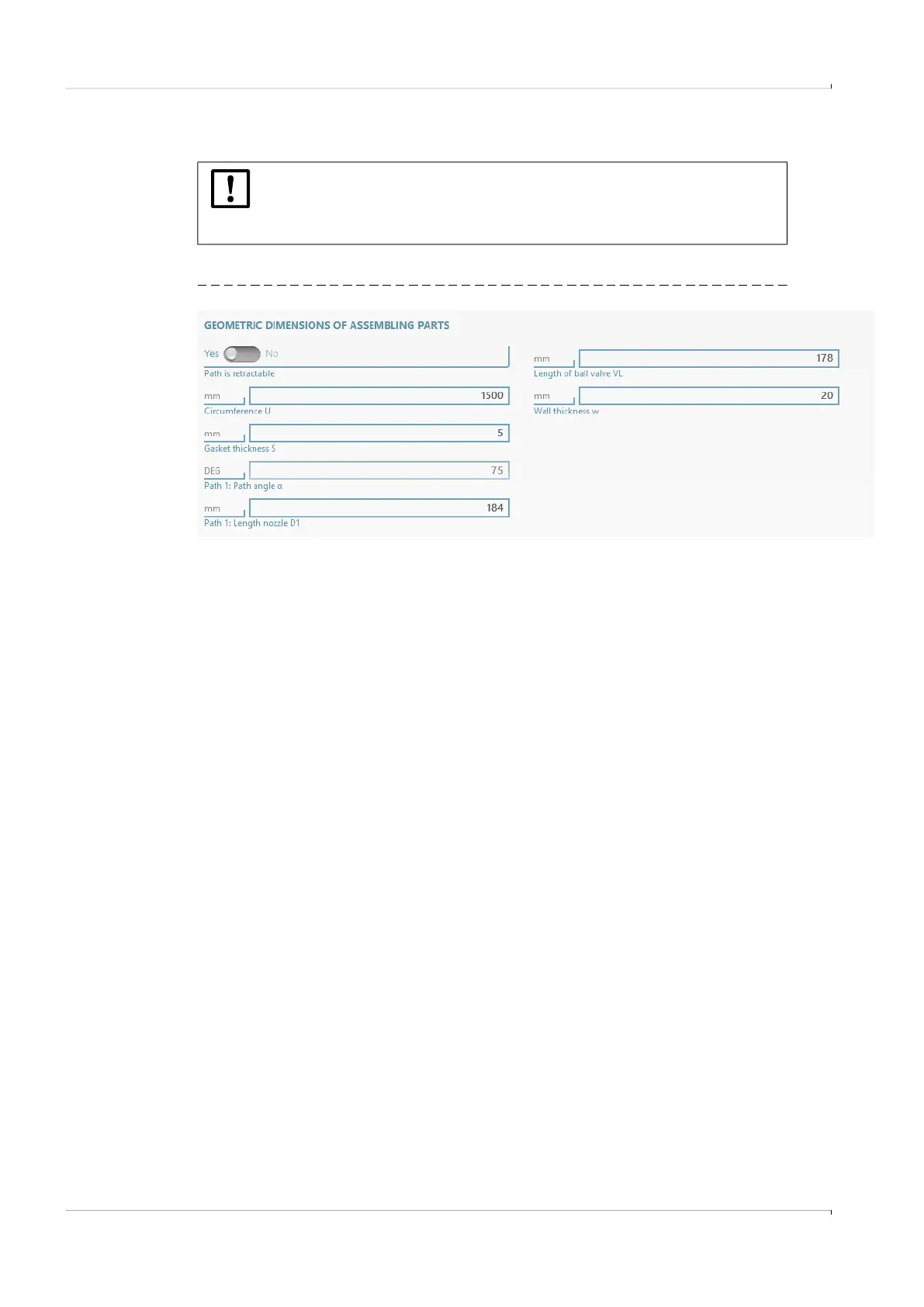
For installations with ball valves, set slider “Path is retractable” to “Yes”.
Fig. 78 Installation parameters
▸
Enter the dimensions determined during installation:
– Wall thickness w, circumference U
p. 54, §5.6.7.2 for cross-duct versions and
p. 56, §5.6.7.3 for the probe versions
– Nozzle length D1; and the length of the second nozzle D2 for cross-duct versions,
p. 57, §5.6.7.4
– Gasket thickness S, length of ball valve VL
p. 62, §5.6.8
▸
Click “Calculate probe offset”.
The probe offset is calculated.
▸
Click “Calculate parameter values”.
The parameter values are calculated.
NOTICE:
Systems consisting of Interface Unit, FLSE-XT sender/transmitter/receiver
units and spool piece are preconfigured at the factory. Do not change the
configurations for these systems and skip the “Installation”.step.