110 FLOWSIC100 Flare-XT · Operating Instructions · 8023761/V 1-0/2020-10 · © SICK Engineering GmbH
Installation Interface Unit
6.5.5
Electrical connections of the Interface Unit
6.5.5.1 Overview of electrical connections
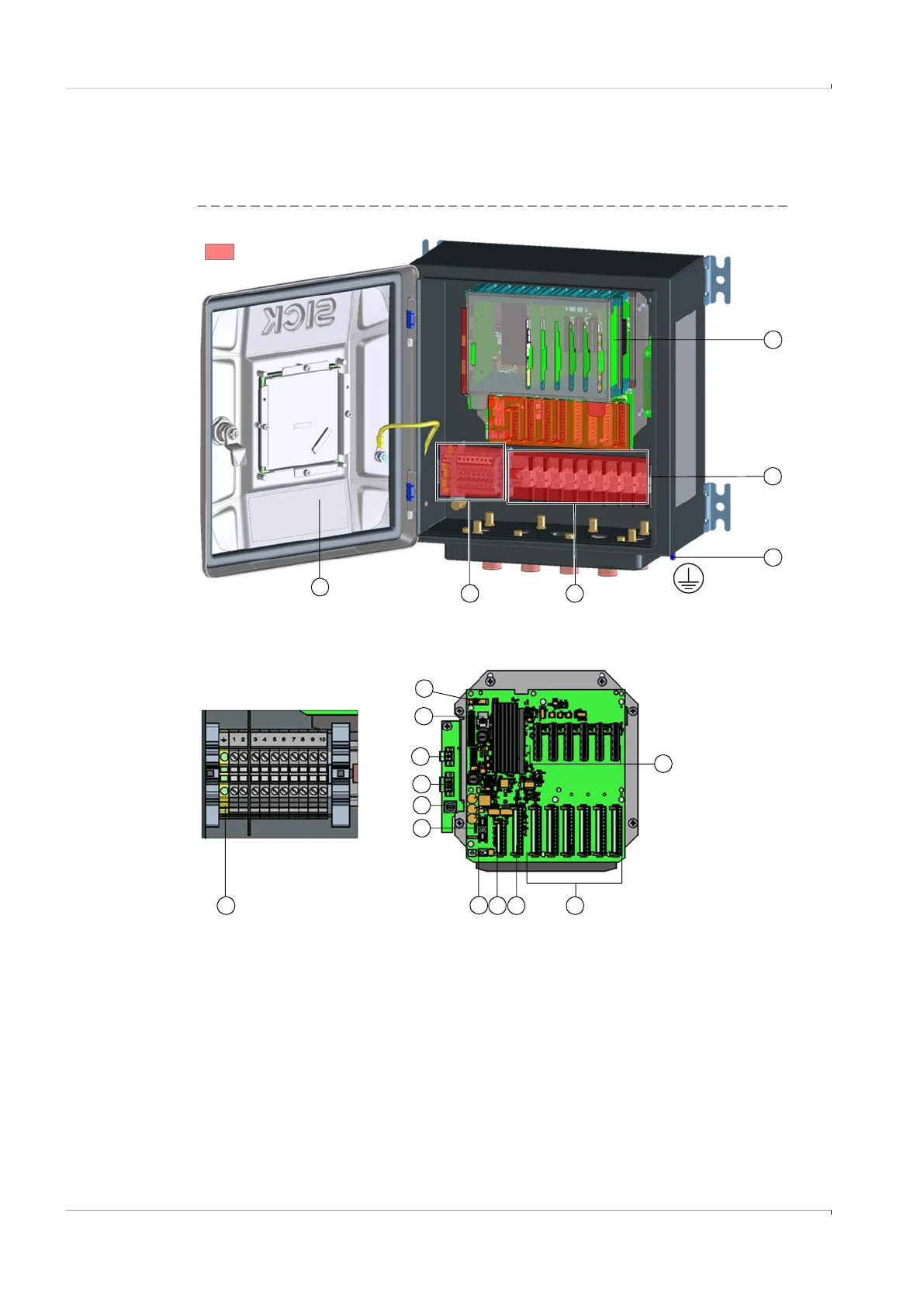
Fig. 63 Connection area and inner electronics of the Interface Unit
1 Mainboard 10 Field terminal connector P2 – Ethernet
2 DIN rail 11 Field terminal connector P1 – Power In 24 V DC
3 Exterior ground terminal (connected with GND) 12 Fuse F1
4 Shielding terminals 13 Fuse F2
5 Terminal blocks 14 Field connection J2 – power supply connection of the
internal power supply unit
6 Terminal assignment sticker 15 Field connection J1 – 24 V output voltage of the internal
power supply unit
7 Slots for I/O modules 1-6 16 Memory card (MIcro SD)
8 Field connections for I/O modules P4 - P9 – direct
connection to module slots 1-6
17 Backup battery for real-time clock (RTC)
9 Field connection for ultrasonic sensors P3 – external serial
bus
18 Terminal block grounding
2
3
5
8
4
11
10 918
Terminal blocks
12
13
6
Connection area
Mainboard
1
16
17
7
15
14