42 FLOWSIC100 Flare-XT · Operating Instructions · 8023761/V 1-0/2020-10 · © SICK Engineering GmbH
Installation FLSE100-XT
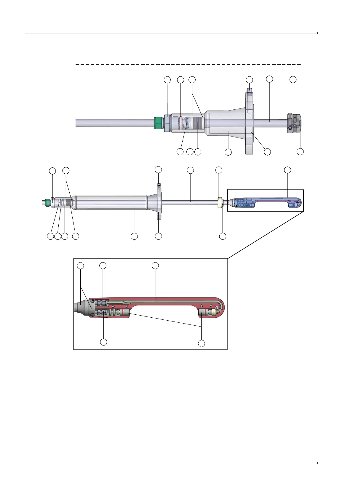
5.3.3
Material for parts with process gas contact
Fig. 14 Parts with process gas contact
12
32
11
5 146 7
10
15
1
16
8
12
1
5
11
10
8
3
7
6
4
1 Pipe screw fitting 10 Duct probe
2 Threaded ring 11 Connection for optional venting
3 Spring 12 Centering
4 Sealing disc 13 Sensor contour probe version F1F-P
5 Sealing profile 14 Adjusting ring
6 Retraction nozzle 15 Thrust ring
7 Retraction flange 16 Probe tube
8 Transducer 17 Transducer pipe screw fitting
9 Sensor contour 18 Transducer and contour holder
Cross-duct versions F1F-S / -M / -H
Probe version F1F-P
13
2
9
4
18 17
17