128 FLOWSIC100 Flare-XT · Operating Instructions · 8023761/V 1-0/2020-10 · © SICK Engineering GmbH
Commissioning FLOWSIC100 Flare-XT
7.5.6
I/O configuration
In the I/O configuration step, the parameters can be set for the interfaces available in
accordance with the ordered configuration. Depending on the configuration, several
modules of one type may be available.
The designation Px behind the interface designation describes the position of the module,
for arrangement see
p. 110, §6.5.5.
7.5.6.1 Ethernet
The MAC address can be read out in this view.
▸
Enter IP address, network mask and gateway.
▸
When no gateway is used, enter “0.0.0.0” as gateway.
7.5.6.2 RS485/RS232
Define the communication settings for connected devices, e.g., for connected gas
chromatographs.
Table 14 Selection options for connected devices
7.5.6.3
DI/DO (layout depending on the selected configuration)
Digital outputs DO1, DO2 and DO4 can be activated.
DO3 can be configured as status output or pulse output (PO1). The desired measured value
can be assigned to the pulse outputs. The desired function can be assigned to the digital
output in the “Function” menus.
DO5 and DO6 can be configured as digital inputs DI1 and DI2.
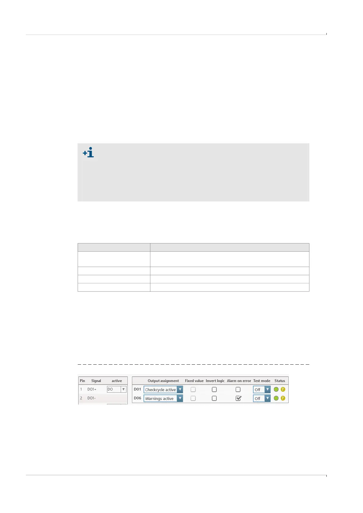
Example for the configuration of a digital output:
Fig. 79 DO1 (example)
Factory settings:
● Ethernet port 1:
– IP address: 192.168.1.100
– Network mask: 255.255.255.0
● Ethernet port 2:
– IP address: 192.168.2.100
– Network mask: 255.255.255.0
Selection Description
Flowgate Modbus Ser
Connection Service PC via RS485-USB Adapter Using
Flowgate over greater distances than with infrared adapter
Scada MODBUS Ser Connection Interface Unit to higher level control system
MCU-P compatible Interface Unit MODBUS Register mapping analog to MCUP
GC Connecting a standardized gas chromatograph