94 FLOWSIC100 Flare-XT · Operating Instructions · 8023761/V 1-0/2020-10 · © SICK Engineering GmbH
Installation Interface Unit
6.3.4
Device description
The Interface Unit is used for the acquisition, processing and output of measured values
and serial data. A multitude of different digital, analog and serial sensors can be connected
to the Interface Unit.
As a modular expandable system, the Interface Unit contains a processor board on its
motherboard as well as a basic set of serial interfaces. In addition, module slots are
available for connecting up to six I/O modules (depending on device version). For the con-
nection of the field-side interfaces of the I/O modules, up to six slots with pluggable termi-
nal strips are available on the mainboard.
Up to nine cable inlet openings, either NPT or with metric cable glands, are available for
routing all connection cables (depending on device version). The internally installed real-
time clock also has a replaceable backup battery.
The Interface Unit is optionally supplied via DC voltage 12 ... 24 V DC or by an internally
installed SELV wide range power supply with 24 V DC output voltage for the connection
range from 115 ... 230 V AC.
It is possible to connect additional sensors to the Interface Unit. These can be connected
to the internal terminal blocks. The sensors are supplied either via the internally generated
24 V DC or by routing the external supply voltage. The data connection between sensors
and Interface Unit runs via the internal RS485. Additional terminal blocks provided can be
used to connect several sensors.
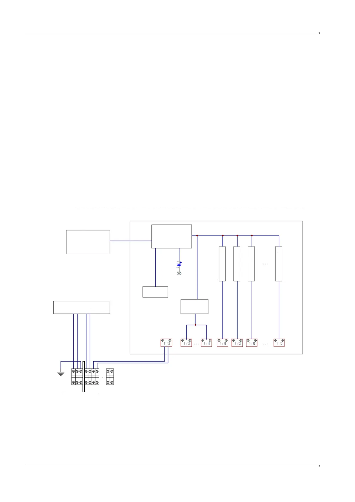
Fig. 51 Layout
Display
CPU Module
Module Slots
Slot 1
Slot 2
Slot 3
Slot n
RTC
Back-up
Serial
Interface
PA
Optional AC/DC Converter
Uout = 24 V DC
Internal
Memory
Power IN
12 ... 24 V DC
115 .. 230 V AC IN
optional
24 V DC Out
Mainboard