76 FLOWSIC100 Flare-XT · Operating Instructions · 8023761/V 1-0/2020-10 · © SICK Engineering GmbH
Installation FLSE100-XT
5.6.10
Fitting the venting valve
A venting valve is available as an option from SICK (Order No. 2108210).
Use a suitable valve with 1/8" NPT thread when the valve available from SICK is not used.
1 Remove the blind plug on the sender/receiver unit, → Fig. 40.
2 Wrap the sealing tape (PTFE) 2.5 layers around the external thread of the venting valve
in thread direction.
3 Screw the venting valve in.
Pay attention to the alignment of the key surfaces: The valve must not hit the ball valve;
align the wrench surfaces as parallel as possible to the flange sealing surface.
4 Tighten the screw plug of the valve so that no gas escapes there.
5 Then carry out a leak tightness check with suitable means.
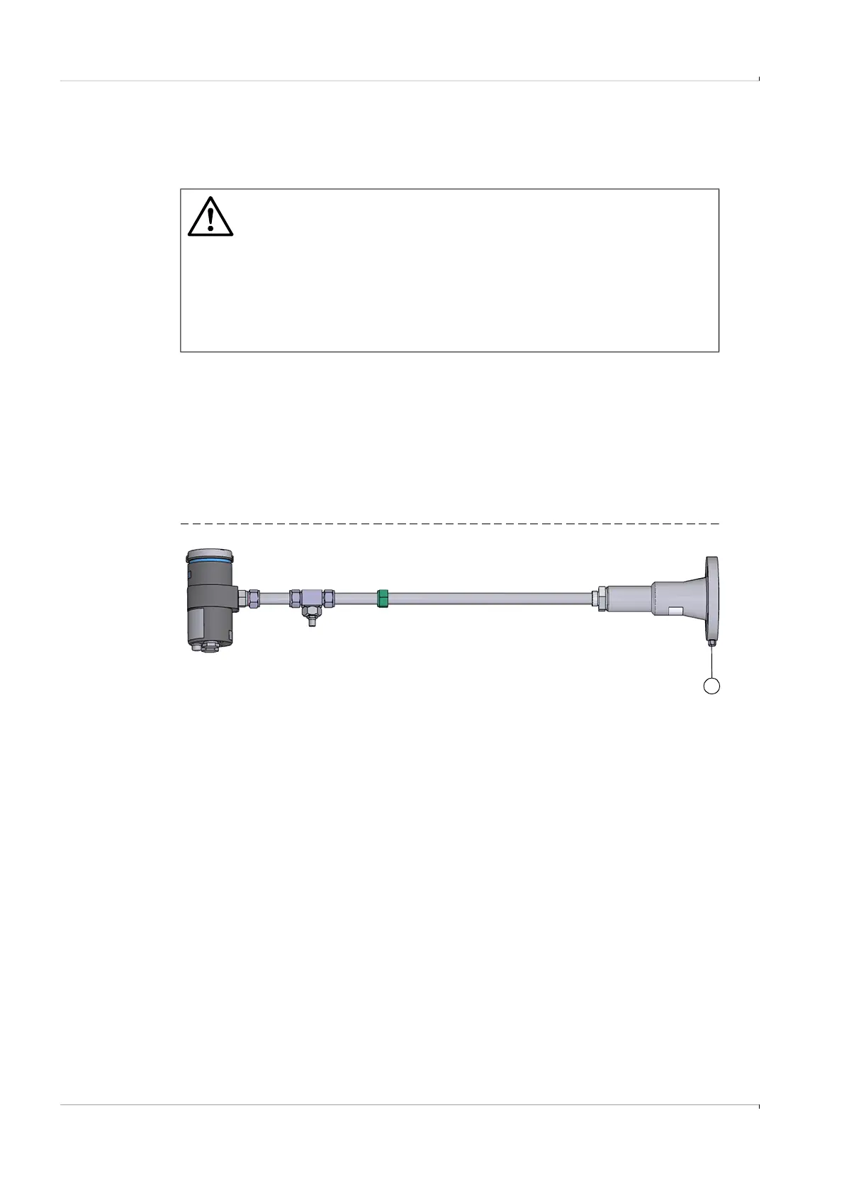
Fig. 40 Venting valve connection
WARNING: Hazard through gas in the pipeline
▸
Install the venting valve only when the sender/receiver unit is not yet
installed in the pipeline or when the pipeline is free from pressure and
dangerous gas.
▸
During installation and operation, adjust the position of the vent so that
personnel do not come into direct contact with the medium.
▸
Open the vent slowly.
▸
Small quantities of medium can escape via the spindle in the open
position. Take appropriate protective measures for the operating personnel.
1
1 Blind plug; venting valve connection