62 FLOWSIC100 Flare-XT · Operating Instructions · 8023761/V 1-0/2020-10 · © SICK Engineering GmbH
Installation FLSE100-XT
5.6.8
Fitting the sender/receiver units
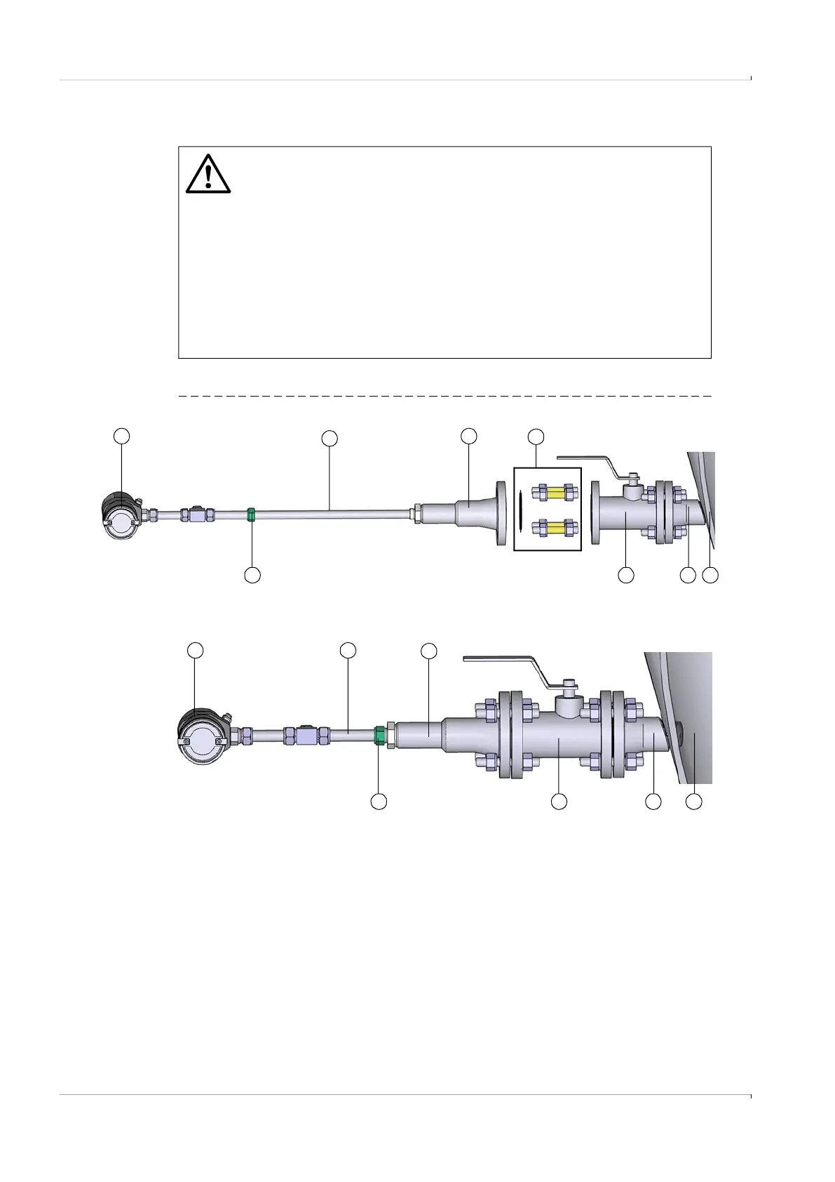
Fig. 30 Overview
WARNING: General risks during installation
▸
Observe and follow the valid regulations and safety regulations as well as
the safety notices in
p. 28, §5.2.
▸
Take special precautions for plants with increased hazard potential (toxic/
aggressive/explosive gases, higher pressure, higher temperature).
Otherwise serious injuries are possible.
▸
Take suitable protection measures against possible local hazards or
hazards arising from the equipment.
▸
Observe the allowable operating parameters during all work.
▸
Ball valve and sender/receiver unit do not function correctly following
incorrect installation. Both parts can be damaged. Serious injuries are
possible.
5
1
1 Electronics unit 5 Mounting kit (gasket, fastening screws, nuts, washers,
centering sleeves)
2 Duct probe 6 Ball valve
3 Cutting ring screw connection 7 Nozzle
4 Retraction nozzle 8 Pipeline
2
3
4
1 2
3
4
76
6 8
8
7

 Loading...


