180 FLOWSIC100 Flare-XT · Operating Instructions · 8023761/V 1-0/2020-10 · © SICK Engineering GmbH
Annex
15 .3
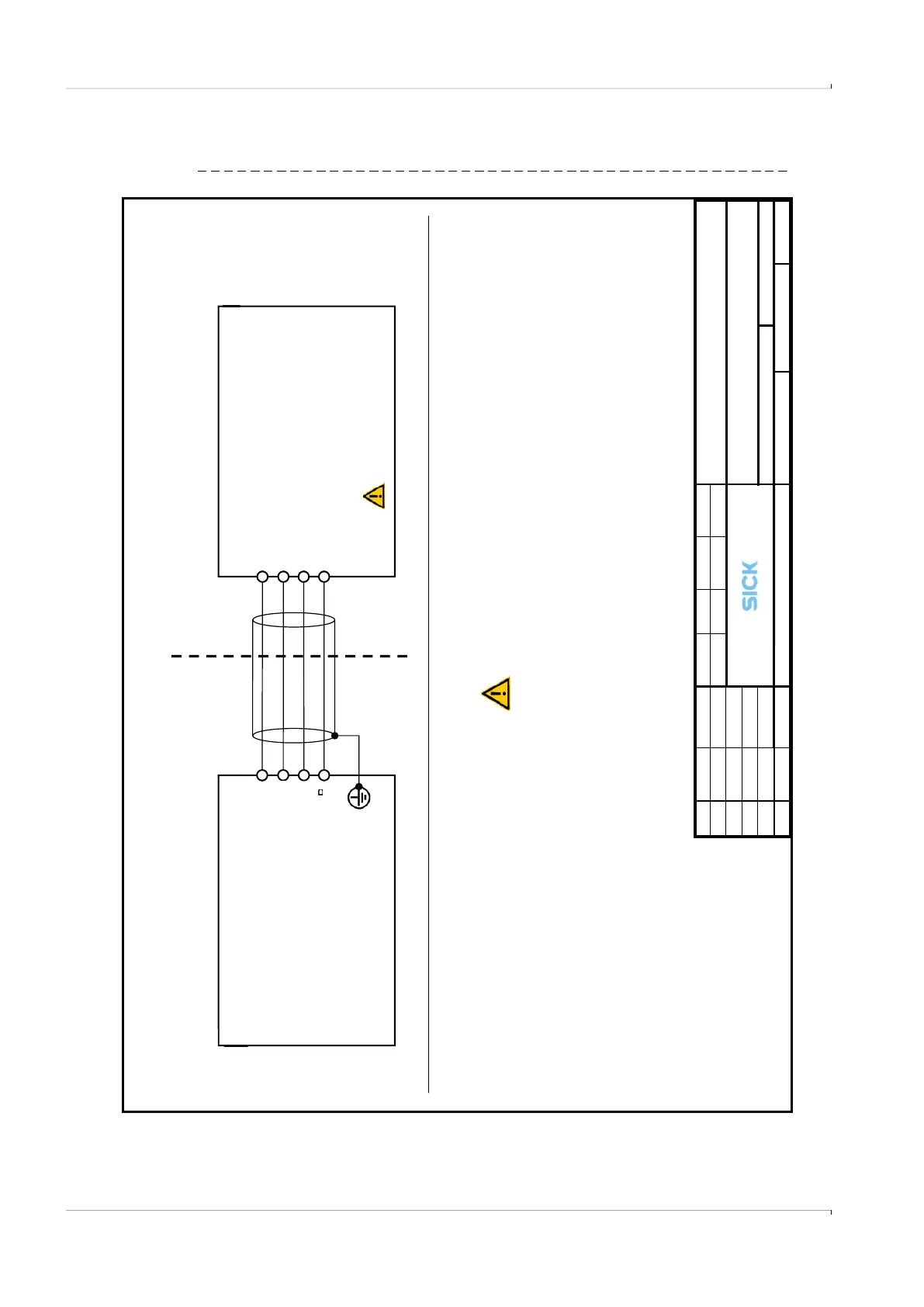
Control drawings
Fig. 113 Control Drawings FLSE-XT (page 1 of 5)
D-01458 Ottendorf-Okrilla
FLOWSIC100 Flare XT-S/-R/-M/-H/-P
Hazardous (classified) Location
FLOWSIC100 Flare XT-H
Class I, Division 1, Groups B, C and D, T4;
Class I, Zone 1, Ex/AEx d IIB + H2, T4;
Class I, Division 2, Groups A, B, C and D, T4;
Class I, Zone 2, Ex/AEx
FLOWSIC100 Flare XT-S /-R /-M /-P
Class I, Division 1, Groups B, C and D, T4;
Class I, Zone 1, Ex/AEx d[
Class I, Division 2, Groups A, B, C and D, T4;
Class I, Zone 2, Ex/AEx nA[ia] IIC, T4;
Division 1 / Zone 1 Installations
In the US install in accordance with the NEC
(NFPA70, Article 504) and
l in accordance with CEC part 1.
WARNING: EXPLOSION HAZARD
components may impair Intrinsic Safety
AVERTISSEMENT: RISQUE D` EXPLOSION
La substitution de composants peut compromettre la sécurité intrinsèque.