Installation Interface Unit
FLOWSIC100 Flare-XT · Operating Instructions · 8023761/V 1-0/2020-10 · © SICK Engineering GmbH 97
6.4.4
Fitting the Interface Unit
Fit the Interface Unit in an easily accessible and protected position. The following must be
taken into account:
▸
Maintain the ambient temperature range in accordance with the Technical Data under
consideration of possible radiant heat (shield when necessary).
▸
Protect the Interface Unit against direct sunlight and atmospheric conditions (weather-
proof cover available as option).
▸
Select an installation location free from vibrations when possible and stabilize
vibrations when necessary.
▸
Provide sufficient clearance for cables and opening the front panel.
▸
Select an installation location free of chemical influence.
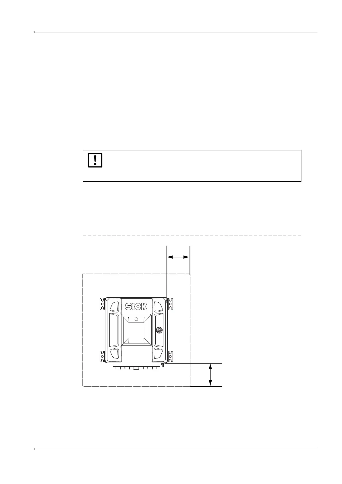
6.4.4.1 Wall fitting
▸
Ensure sufficient assembly clearance.
Dimension drawing, see
p. 169, §12.8.2.
▸
Maintain a general clearance of 15 cm around the enclosure to ensure better heat
circulation.
▸
The distance between enclosure base and wall must be 10 mm; the wall must be flat.
The air circulation behind the Interface Unit must not be obstructed.
Fig. 52 General clearance to Interface Unit
NOTICE:
▸
Use suitable fixing material for mounting.
▸
Observe the total weight of the Interface Unit as well as local and legal
regulations for the design of the wall construction and fastening material.
15 cm
15 cm