Commissioning FLOWSIC100 Flare-XT
FLOWSIC100 Flare-XT · Operating Instructions · 8023761/V 1-0/2020-10 · © SICK Engineering GmbH 129
Table 15 Selection options
● Invert logic: Inverts the logic of the output signal
● Alarm on error: In case of an error of the digital output, an error is displayed in the
system status of the FLOWSIC100 Flare-XT
● Test mode:
– Off: Test mode not active
– Permanently on: Test of digital output, permanently on
– Permanently off: Test of digital output, permanently off
Example for the configuration as pulse output:
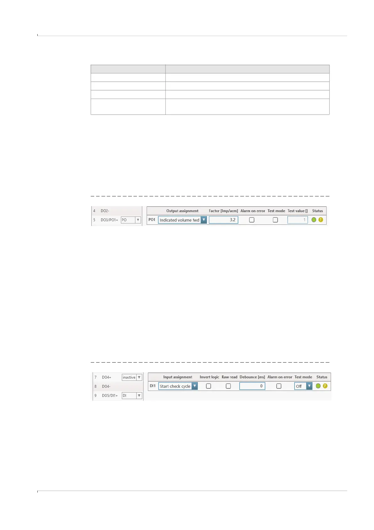
Fig. 80 PO1 (example)
● Function: Output values of the pulse output; the following measured values can be
output (forward = positive flow direction):
– Indicated volume fwd
– Base volume fwd
– Mass fwd
– CO2 mass fwd
● Factor: The factor indicates how many pulses are output per selected unit; in the
example (→ Fig. 80), 3.2 pulses per measured cubic meter of gas are output in the flow
direction.
● Alarm on error: In case of an error of the pulse output, an error is displayed in the
system status of the FLOWSIC100 Flare-XT
● Test mode: Test mode active
● Test value: Impulses per calculation cycle of the application; the default duration of a
calculation cycle is 500 ms.
Example for the configuration as digital output:
Fig. 81 DI1 (example)
Selection Description
Checkcycle active Check cycle of the sender/receiver units
Warnings active Warnings are active on the FLOWSIC100 Flare-XT
Alarms active Alarms are active on the FLOWSIC100 Flare-XT
Flow direction
Flow direction of the gas; positive flow direction (0), return
flow (1)