Commissioning
FLOWSIC500 · Operating Instructions · 8025733/1GMJ/V4-2/2022-07 · © SICK Engineering GmbH 73
Subject to change without notice
4.3.2.3 Warnings
The “Warnings” area serves to set the limit values outside of which the FLOWSIC500 is to
output warnings (flow rate) or errors (pressure and temperature).
Limit values can be set for:
● Flow rate
● Pressure
● Temperature
● Reverse flow volume (buffer volume)
● Limit value for low flow rate (zero-flow cutoff)
In addition, the warnings signalled by the device can be individually activated or deactivated
in the "User warnings activation" area.
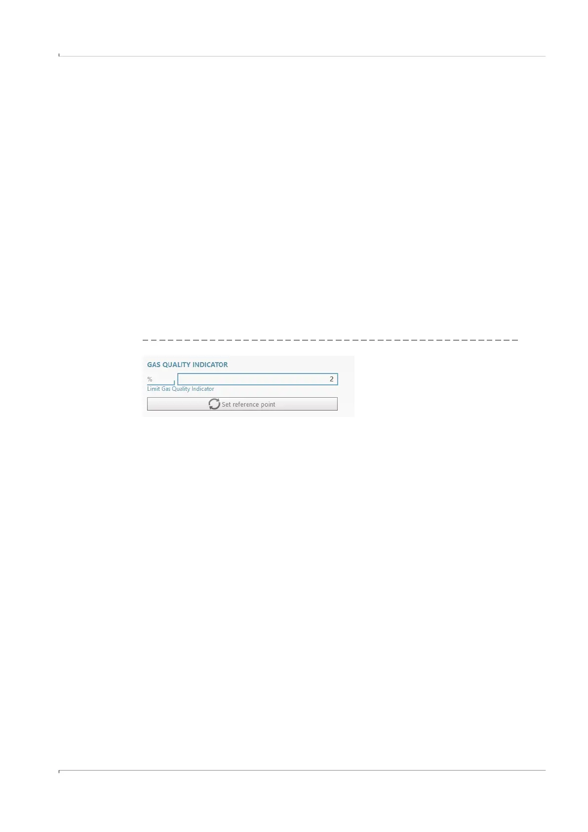
The Gas Quality Indicator allows the gas quality to be monitored in real time. By clicking on
"Set reference point" the reference point is set automatically based on the current measu-
red values. The permissible deviation in percent can be configured. If the limit value is
exceeded or fallen below, the FLOWSIC500 generates a warning. Setting the reference
point requires that gas of typical quality flows through the FLOWSIC500. If this is not given
during commissioning, the reference point can be set afterwards in the menu "Parameter
modification/Warnings".
Bild 39 Gas Quality Indicator
4.3.2.4
Communication
▸
The configuration of the single plug-in connectors is preset according to the
configuration ordered. Check the configuration and adapt when necessary.
▸
For pulse outputs, the maximum frequency and the minimum pulse width must be set
during commissioning.
▸
The status outputs are configured as standard so that status “Measurement invalid” is
output. Selecting status “Measurement valid” shortens the battery service life
considerably because the output is then permanently activated.
Plug 1: B-coded
▸
Configuration as status or pulse output possible: Select the desired configuration.
▸
Enter the maximum frequency and minimum pulse width in the “Pulse 1” area when
configuring as a pulse output.
When configured as a pulse output, make sure the overload frequency of 120% Q
max
is
covered and the connected device understands the frequency.
The following conditions must be satisfied:
● The “Maximum frequency” must be set to a value higher or equal to the “Frequency at
Qr”.
● The “Minimum pulse width” must be set to a value lower or equal to 1/(2 x “Frequency
at Qr”).