74 FLOWSIC500 · Operating Instructions · 8025733/1GMJ/V4-2/2022-07 · © SICK Engineering GmbH
Commissioning
Subject to change without notice
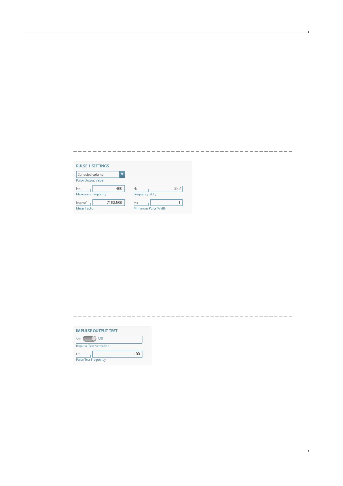
Example
Frequency at Qr = 382 Hz
Maximum frequency:
Set “Maximum frequency” to a value ≥ 382 Hz.
Recommendation. Round up to 400 Hz.
Minimum pulse width:
1 Hz corresponds to 1000 ms
382 Hz corresponds to 2.6 ms
1/(2 x “Frequency at Qr”) = 1.3 ms
Set “Minimum pulse width” to an integer value < 1.3 ms.
Recommendation: set 1 ms.
Fig. 40 Pulse settings example
Plug 2: A-coded
▸
Configuration as status or pulse output possible: Select the desired configuration.
▸
Enter the maximum frequency and minimum pulse width in the “Pulse 2” area when
configuring as a pulse output.
For configuration, see Section “Plug 1: B-coded”.
Communication tests
● Pulse output:
– Enter the desired test frequency.
– Push the slider to “On” to start the test. The test frequency is output on all pulse
outputs.
Fig. 41 Pulse output test
● Flow rate
– Enter the desired test flow rate and start the test.
● Digital output
– Select the desired digital output.
– Push the slider to “On”.