129
GB
MSL coded version
8 007 898/O369/05-04-04 Operating instruction • MSL cod. © SICK AG • Industrial Safety Systems • Germany • All rights reserved
3 Installation
3.1 Mechanical mounting
The sender and receiver are mounted
using rigid or pivoted mounting brackets
(
Fig. 2, appendix
). The sender and
receiver (together with any additional
modules) are attached to the brackets
using sliding nuts in the profiles. The
device must be positioned as shown in
the dimensional drawing (
Fig. 3,
appendix
).
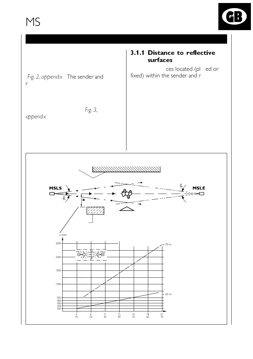
3.1.1 Distance to reflective
surfaces
Reflective surfaces located (placed or
fixed) within the sender and receiver
range, may cause reflection and thus
prevent an obstacle from being reliably
detected.
For this reason, a minimum distance ,a
,
from reflective surfaces to the optical
axis (linear connection between MSLS
and MSLE) must be maintained (see
illustration below). The distance ,a
,
is
dependent on the distance between the
sender and receiver.
Reflective
surface
Distance in m
Point-of-operation
boundary
241967_MSLcv_GB_3.p65 10.12.04, 09:40129
Schwarz

 Loading...


