131
GB
MSL coded version
8 007 898/O369/05-04-04 Operating instruction • MSL cod. © SICK AG • Industrial Safety Systems • Germany • All rights reserved
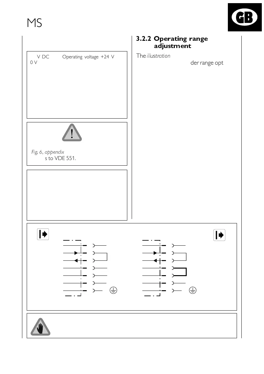
Operating range 15 to 70 m
Operating range 0,5 to 18 m
The link between pins 5 and 6 must be made at the connection terminal block
for PG and Hirschmann connection versions. For Interconnectron and Harting
versions the link must be made in the socket.
*)
*)
*) reserved, do not use
1
3
4
5
6
2
7
+24 VDC
Test ➞
Test
n. c. *)
n. c. *)
0 V
PE
➞
1
3
4
5
6
2
7
+24 VDC
Test ➞
Test
0 V
PE
➞
Change of material
To ensure optimum ESD protection the
material used for the terminal chamber –
equipped with Interconnectron or
Harting plugs – has been changed from
plastic to metal.
3.2.2 Operating range
adjustment
24 V DC Operating voltage +24 V
0 V Signal ground (0 V)
Test Test-contact connection
RW Operating range adjustment
PE Protective earth conductor
OSSD1 Safety Output 1
OSSD2 Safety Output 2
RES Reset input
EDM External device
monitoring input
OWS Contamination signal output
If Interconnectron plugs are used
(
Fig. 6, appendix
), use only reliable power
supplies to VDE 551.
The
illustration
shows the two connection
possibilities for the sender range options.
The meaning of the individual connections
is as follows:
241967_MSLcv_GB_3.p65 10.12.04, 09:40131
Schwarz
 Loading...


