6 Assi
nin
Parameters to the Control and the PLC Pro
ram
6
03.96
6.10 Linear motors (1FN1 and 1FN3 motors)
6-165
Siemens AG 2000 All Rights Reserved
SINUMERIK 840D Installation and Start-Up Guide (IAD) – 04.00 Edition
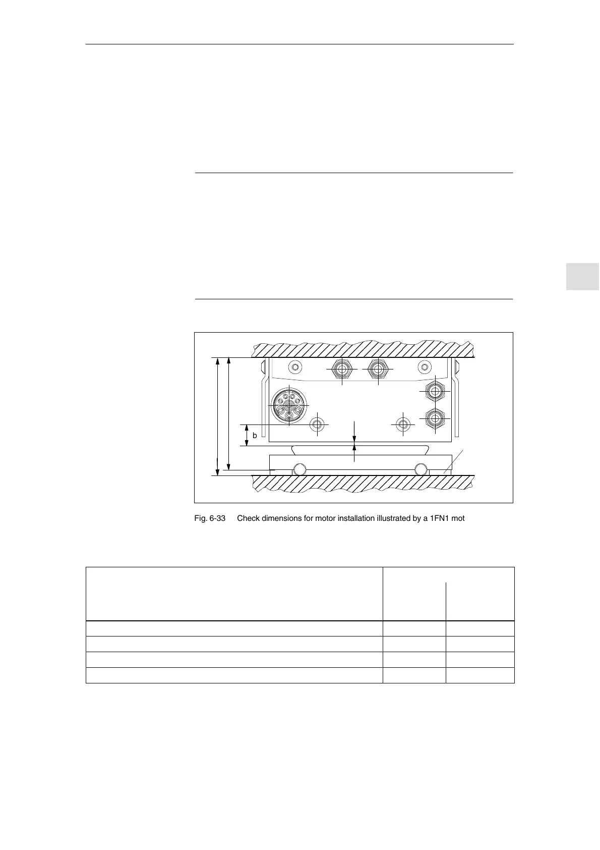
6.10.4 Mounting dimensions
Mounting dimension e
1
or e
2
can be checked by means, for example, of gauge
blocks and feeler gauges before the motor is installed.
Note
The applicable mounting dimensions can be found in the following documents:
S /PJLM/ SIMODRIVE Planning Guide for Linear Motor
S The data sheet of the appropriate 1FN1 or 1FN3 motor.
Please note with respect to mounting dimension and air gap:
The electrical and system-related properties of the linear motor are guaranteed
solely as a function of the mounting dimension and not the measurable air gap.
The air gap must be large enough to allow the motor to move freely.
Thermo-
insulating
bars
e
1
e
2
l
ÌÌÌÌÌÌÌÌÌÌÌÌÌÌÌ
ÌÌÌÌÌÌÌÌÌÌÌÌÌÌÌ
ÌÌÌÌÌÌÌÌÌÌÌÌÌÌÌ
ÌÌÌÌÌÌÌÌÌÌÌÌÌÌÌ
ÌÌÌÌÌÌÌÌÌÌÌÌÌÌÌ
b
Fig. 6-33 Check dimensions for motor installation illustrated by a 1FN1 motor
Table 6-22 Check dimensions for mounting dimension and air gap for a 1FN1 linear motor
Linear motors 1FN1 ...
Check dimensions
1FN1 07j 1FN1 12j
1FN1 18j
1FN1 24j
Mounting dimension e
1
[mm] 80.7 0.3 106.7 0.3
Mounting dimension e
2
[mm] (without thermo-insulating bars) 76.7 0.3 101.7 0.3
Measurable air gap l [mm] (not including mounting dimension tolerance) 1.1
+0.3
/
–0.45
1.1
+0.3
/
–0.45
Distance b [mm] (not including mounting dimension tolerance) 13 1 13 1
For mounting dimensions of 1FN3 linear motors, see dimension drawings in
appendix of 1FN Planning Guide, mounting height h
M
or h
M1
.
Check of
mounting
dimension
and
air gap
04.00

 Loading...


