6 Assi
nin
Parameters to the Control and the PLC Pro
ram
6
03.96
6.9 Axes and spindles
6-142
Siemens AG 2000 All Rights Reserved
SINUMERIK 840D Installation and Start-Up Guide (IAD) – 04.00 Edition
6.9.14 Spindle configuration
Setpoints: MD 30100: CTRLOUT_SEGMENT_NR
MD 30110: CTRLOUT_MODULE_NR
MD 30120: CTRLOUT_NR
MD 30130: CTROUT_TYPE
Actual values:
MD 30210: ENC_SEGMENT_NR
MD 30220: ENC_MODULE_NR
MD 30230: ENC_INPUT_NR
MD 30240: ENC_TYPE
Note
For further information about spindle configuration, see above in this chapter in
the “Drive configuration” section.
6.9.15 Encoder matching (spindle)
For the purpose of matching the spindle encoder, the same machine data apply
as for the axis. MD 30300: IS_ROT_AX and MD 30310: IS_ROT_MODULO
must always be set for the spindle so that the encoder is always matched to one
revolution. IS_ROT_AX and MD 30310: ROT_IS_MODULO must always be set
for the spindle so that the encoder is always matched in relation to one
revolution. In order to obtain a display which is always referring to 360 degrees,
MD 30320: DISPLAY_IS_MODULO must be set. If the motor encoder of the
611D system is used for the purpose of encoder matching, then the encoder
matching data must be entered for each individual gear stage if several gear
stages are present. The maximum multiple of the 611D drive is always used as
the maximum multiple of encoder lines. This multiple is 2048.
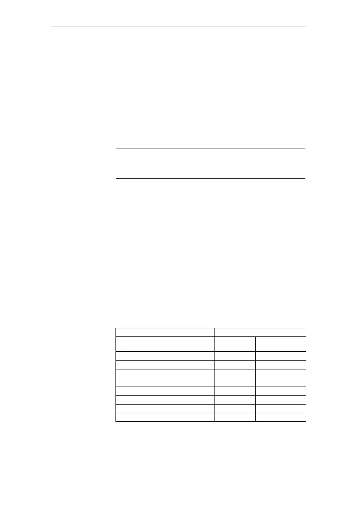
Table 6-20 Machine data for encoder matching
Machine data Spindle
Encoder on
motor
Encoder on spindle
30300: IS_ROT_AX 1 1
31000: ENC_IS_LINEAR 0 0
31040: ENC_IS_DIRECT 0 1
31020: ENC_RESOL Lines/rev. Lines/rev.
31080: DRIVE_ENC_RATIO_NUMERA Motor rev. Load rev.
31070: DRIVE_ENC_RATIO_DENOM Encoder rev. Encoder rev.
31060: DRIVE_AX_RATIO_NUMERA Motor rev. See following note
31050: DRIVE_AX_RATIO_DENOM Load rev. See following note
Machine data for
setpoints and
actual values
Encoder matching
via machine data

 Loading...


