6 Assi
nin
Parameters to the Control and the PLC Pro
ram
6
03.96
6.10 Linear motors (1FN1 and 1FN3 motors)
6-174
Siemens AG 2000 All Rights Reserved
SINUMERIK 840D Installation and Start-Up Guide (IAD) – 04.00 Edition
6.10.8 Test measurements on linear motor
If the linear motor has been started up in accordance with instructions, but inex-
plicable error messages still appear, it will be necessary to test all signals by
means of an oscilloscope.
When the primary parts are connected in parallel,
EMF_U of motor 1 must be in phase with EMF_U of motor 2.
The same applies to EMF_V and EMF_W.
This in-phase condition must be checked by means of test measurements.
Procedure for taking test measurement:
S Isolate terminals 48 and 63 on the NE module and terminal 663 on the
closed-loop control plug-in unit.
S Caution: Wait for DC link to fully discharge!
S Disconnect power cable from drive.
Separate any parallel connection of primary parts.
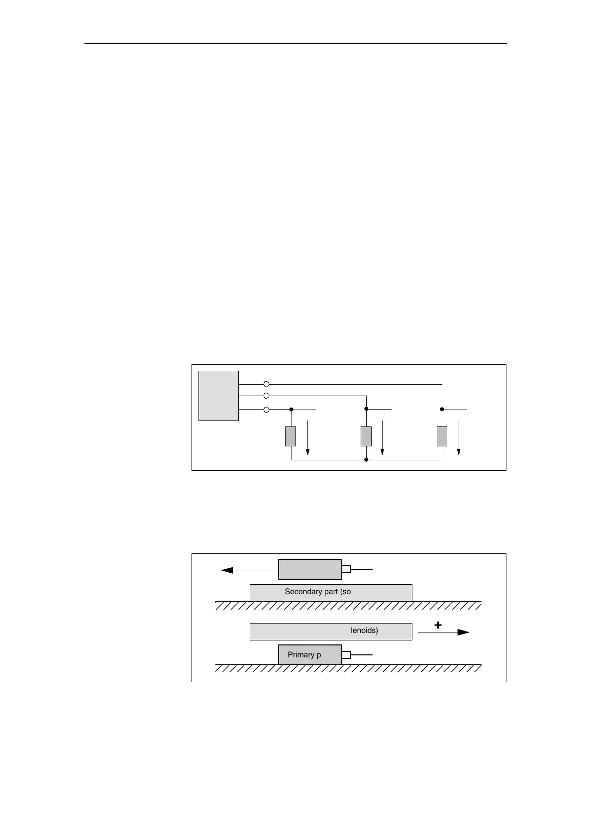
S Create an artificial neutral point using 1k ohm resistors.
U
V
W
1 kΩ
Linear
motor
EMF_U
1 kΩ 1 kΩ
EMF_W EMF_V
Fig. 6-42 Arrangement for test measurements
The phase sequence must be U–V–W with a positive traversing direction.
The direction of the drive is positive if the primary part moves in the opposite
direction to the outgoing cable in relation to the secondary part.
Secondary part (solenoids)
+
Secondary part (solenoids)
+
Primary part
Outgoing cable direction
Primary part Outgoing cable direction
Fig. 6-43 Determining the positive direction of the drive (CW rotating field)
Why measure?
Check phase
sequence
U–V–W
04.00

 Loading...


