3
03.96
3.7 Customer operator panel interface
3-68
Siemens AG 2000 All Rights Reserved
SINUMERIK 840D Installation and Start-Up Guide (IAD) – 04.00 Edition
3.7 Customer operator panel interface
A customer operator panel can be connected via the interface. 64 digital inputs
and 64 digital outputs with C-MOS level (5 V) are available on the module for
this purpose.
The module must have firmware version V 03_01_01 or higher.
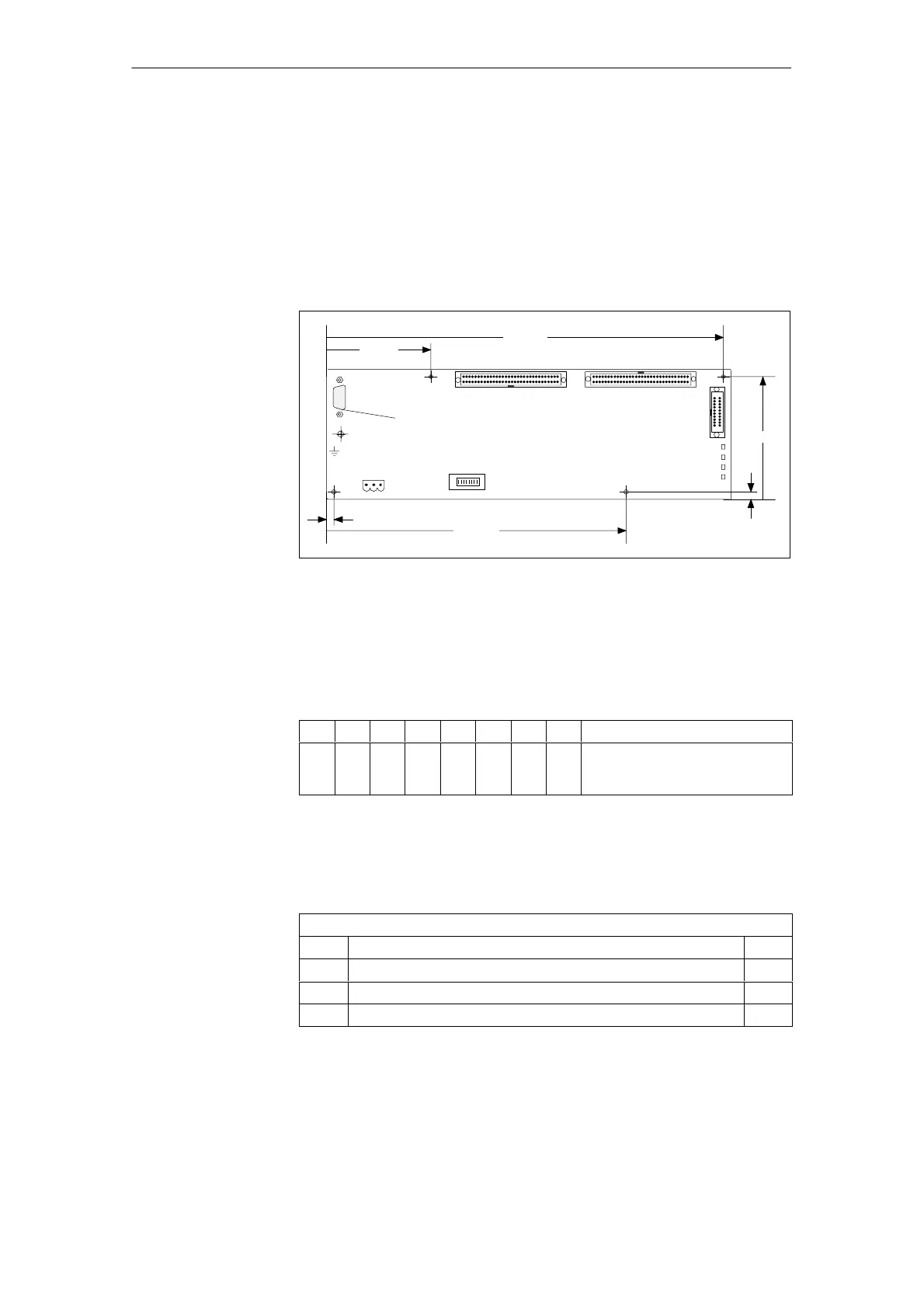
X231
LEDs
X20
MPI connection
X10
X221X211
H3
H1
H4
H2
289.4
64.7
207.3
92.7
7.2
3.5
Holes 3.6
Equipotential bonding connection
S3
ON
Fig. 3-12 Front view of interface to customer operator panel
If only the customer operator panel is to be connected, then the bus address
must be set to 6 as for the MCP (standard application).
Table 3-9 Setting for 840D: Switch S3 on interface for customer operator panel
1 2 3 4 5 6 7 8 Meaning:
on off on off on on off on Baud rate: 1.5 Mbaud (OPI)
Cyclical transmit pattern: 100 ms
Bus address: 6
Connector designation: X10
Connector type: 3-pin Phoenix terminal block, straight
Table 3-10 Pin assignment of X10 connector on interface to customer operator panel
X10
Pin Name Type
1 SHIELD VI
2 M24 VI
3 P24 VI
Interface
Location of the
interfaces
Switch S3, default
setting
Power
supply
interface
3 Settin
s, MPI / OPI
08.97

 Loading...


