3
03.96
3.3 Connection of a 2nd MCP/customer OPI and/or 1 HHU (up to SW 3.1)
3-46
Siemens AG 2000 All Rights Reserved
SINUMERIK 840D Installation and Start-Up Guide (IAD) – 04.00 Edition
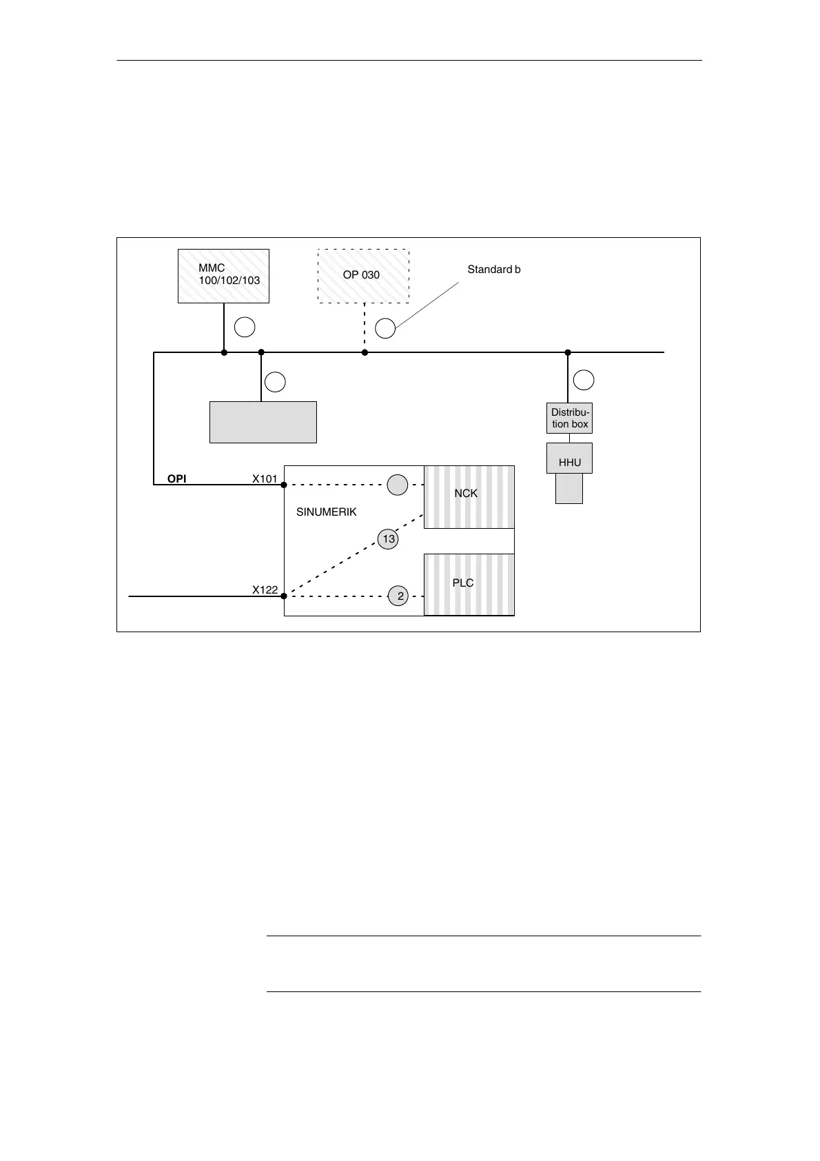
3.3.3 Example of a configuration of MCP and HHU via OPI
S MCP with firmware version V 03_01_01
S HHU with firmware version V 01_01_02
MMC
100/102/103
OP 030
1
10
1 MCP
15
6
OPI
NCK
PLC
X101
SINUMERIK 840D
MPI
187.5 kbaud
13
13
2
X122
OPI
Distribu-
tion box
HHU
Standard bus
addresses
Fig. 3-6 Example of configuration of MCP and HHU via OPI
The following parameter settings must be made for the MCP and HHU operat-
ing components in FB1.
MCPNum:=1 (one MCP)
MCP1In:=P#E0.0 (MCP input signals)
MCP1Out:=P#A0.0 (MCP output signals)
MCP1StatRec:=P#A12.0 (status double word)
MCP1StatSend:=P#A8.0 (status double word)
MPIBusAdr:=6
BHG:=2 (HHU on OPI)
BHGIn:=P#M20.0 (HHU input signals)
BHGOut:=P#M0.0 (HHU output signals)
BHGStatRec:=P#M26.0 (status double word)
BHGStatSend:=P#M30.0 (status double word)
The other HHU parameters are set to appropriate defaults.
See FB basic program.
Note
Note the DIP switch settings (switches S1 and S2 in the HHU).
Preconditions
Parameterization
of basic PLC
program FB1
3 Settin
s, MPI / OPI

 Loading...


